Unit 2 · 7 teaching hours · 41 min read
The Physical Layer
What the syllabus asks for 9
- Functions of the physical layer
- Data and signals
- Data rate limits
- Line coding and digital signalling
- Transmission media
- Multiplexing
- Switching
- Telephone, cable and mobile data networks
- Seeing the ideas: signals, media, multiplexing and switching
Everything above the physical layer pretends that bits exist. The physical layer is where they stop being a pretence: voltages on copper, pulses of light in glass, and radio waves in the air.
How many bits per second you can push through a channel is not a matter of opinion; it is bounded by two famous formulas, Nyquist's and Shannon's, which you will compute in this unit.
You will also see how signals are encoded, how many conversations share one wire (multiplexing), and how a network decides to switch traffic (circuits versus packets).
- Analog and digital signals, bandwidth, impairments (attenuation, distortion, noise) and data-rate limits.
- Line coding: NRZ, NRZI, Manchester, AMI.
- Transmission media: twisted pair, coaxial, fibre, radio, satellite.
- Multiplexing (FDM, TDM, statistical TDM, WDM) and spread spectrum.
- Circuit, message and packet switching; telephone, cable and mobile data networks.
2.1 Functions of the physical layer
The physical layer defines the mechanical characteristics (connectors, pin layout), electrical characteristics (voltage levels, bit duration), functional characteristics (what each wire does) and procedural characteristics (the order of events) of the interface to the medium.
It decides the data rate (bits per second), whether the transmission is simplex (one way, radio broadcast), half duplex (both ways, one at a time, walkie-talkie) or full duplex (both ways at once, telephone), and how bits are synchronised.
2.2 Data and signals
Data is information; signals are the electromagnetic representation. Analog signals vary continuously; digital signals take a few discrete levels.
A periodic signal is described by amplitude, frequency (cycles per second, hertz) and phase.
A signal that is not a pure sine wave is a sum of sine waves of different frequencies (Fourier); the width of the frequency range it occupies is its bandwidth in hertz.
Bandwidth in hertz (analog range of frequencies) and bandwidth in bits per second (data rate) are different quantities, though related.
Baud rate and bit rate
The signal rate (baud) is the number of signal elements per second. If each element can carry b bits, then bit rate = baud × b. With 16 distinct levels (4 bits per element), a 56 kbps modem needs 56,000 / 4 = 14,000 baud.
Transmission impairments
- Attenuation: loss of strength along the medium, measured in decibels (dB). dB = 10 log₁₀(P₂/P₁). A loss of 3 dB is half the power; −30 dB is a thousandth.
- Distortion: different frequencies travel at different speeds, so the shape of a composite signal changes.
- Noise: unwanted signals: thermal noise (always present), crosstalk (from a neighbouring wire), impulse noise (spikes) and interference.
The signal-to-noise ratio SNR = (average signal power)/(average noise power), usually quoted as SNR_dB = 10 log₁₀ SNR. An SNR of 1000 is 30 dB; 100 is 20 dB.
2.3 Data rate limits
Nyquist: a noiseless channel
For a channel of bandwidth B Hz with L signal levels, the maximum bit rate is C = 2 B log₂ L.
Nyquist's theorem says you cannot send more than 2B signal elements per second without intersymbol interference, so the only way to get a higher bit rate is to use more levels.
| Bandwidth B | Levels L | Bits per element | Maximum bit rate |
|---|---|---|---|
| 3000 Hz | 2 | 1 | 6,000 bps |
| 3000 Hz | 4 | 2 | 12,000 bps |
| 3000 Hz | 16 | 4 | 24,000 bps |
Shannon: a noisy channel
Real channels have noise, which makes many levels indistinguishable. Shannon's capacity theorem gives the absolute maximum for any coding scheme: C = B log₂(1 + SNR).
A voice channel has B = 3000 Hz and SNR = 30 dB. First convert: SNR = 10^{30/10} = 1000. Then C = 3000 × log₂(1001) = 3000 × 9.967 ≈ 29,902 bps.
No technique can exceed about 29.9 kbps on this channel, which is why 56 kbps modems relied on an almost entirely digital telephone network, where the only analog part is the short local loop.
For a 1 MHz channel with SNR = 20 dB (100), C = 10⁶ × log₂(101) ≈ 6,658,211 bps.
For B = 3100 Hz, 56,000 = 3100 × log₂(1 + SNR) gives 1 + SNR = 2^{18.06}, so SNR_dB = 10 log₁₀(2^{56000/3100} − 1) ≈ 54.38 dB. Real voice lines rarely reach that, which is why 56k modems usually connected at less.
In practice use both: Shannon gives the ceiling (bandwidth and SNR), Nyquist tells how many signal levels are needed to reach a target rate below the ceiling.
For a 6 Mbps target on a 1 MHz channel: Shannon bound is fine (6.66 Mbps), Nyquist demands 2 × 10⁶ × log₂ L ≥ 6 × 10⁶, so L ≥ 2³ = 8 levels.
Do not use B in kilohertz with the formula expecting bits per second per kilohertz: keep B in hertz so the answer is in bits per second. And Shannon needs SNR as a ratio (1000), not in dB (30).
2.4 Line coding and digital signalling
To send digital data over a wire the bits become voltage levels. A good code carries the clock (so the receiver stays synchronised), has no DC component and detects some errors.
| Code | Rule | Remark |
|---|---|---|
| NRZ-L | 1 = high, 0 = low | simple; long runs of equal bits lose synchronisation |
| NRZI | a 1 flips the level, a 0 keeps it | solves runs of 1s only |
| Manchester | each bit has a mid-bit transition: 1 = low-to-high, 0 = high-to-low (IEEE 802.3 convention) | self-clocking, needs twice the bandwidth; used in 10 Mbps Ethernet |
| AMI (bipolar) | 0 = zero level, 1 alternately +V and −V | no DC, detects single errors; long zero runs are a problem |
For the bit string 10110010: Manchester (as pairs of half-bit levels, 0 = low, 1 = high) is 01 10 01 01 10 10 01 10, which reads 0110010110100110; NRZI (starting at −) is + + − + + + − −; AMI is + 0 − + 0 0 − 0.
Faster Ethernet standards avoid Manchester's halving of efficiency with block codes: 4B/5B maps every 4 data bits to a 5-bit code with enough transitions (efficiency 80 %), and 8B/10B and 64B/66B do the same for gigabit and 10-gigabit links.
Analog transmission of digital data
Over a band-limited line a carrier sine wave is modified by the data: ASK (amplitude), FSK (frequency), PSK (phase) or QAM, which varies both amplitude and phase. QAM-16 sends 4 bits per symbol.
Wi-Fi and DSL use QAM constellations as dense as 1024 or 4096 points when SNR is high.
Sampling voice: PCM
A telephone voice channel is limited to about 4 kHz. The Nyquist sampling theorem requires sampling at twice the highest frequency: 8000 samples per second, 8 bits each: 64 kbps per voice channel (the "DS0" rate).
2.5 Transmission media
Guided media
| Medium | Construction | Typical use | Notes |
|---|---|---|---|
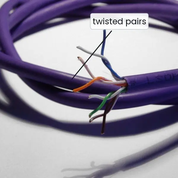
| UTP (Cat5e, Cat6) | four twisted pairs, no shield | office LAN, up to 100 m | twisting cancels interference; Cat5e to 1 Gbps, Cat6 to 10 Gbps over short runs |
| STP | pairs with foil/braid shield | noisy places | more costly |
| Coaxial | copper core, insulator, braid | cable TV, old 10BASE2 Ethernet | better shielding, higher bandwidth than twisted pair |
| Optical fibre | glass core and cladding, light pulses | backbones, FTTH | immune to electromagnetic noise, kilometres without repeaters |
Optical fibre. Light stays in the core by total internal reflection.
Multimode fibre (50 or 62.5 µm core) carries many light paths and suits up to a few hundred metres with LEDs or VCSEL lasers; single-mode fibre (about 9 µm core) carries one path, suffers little dispersion and reaches tens of kilometres with a laser.
Fibre has low attenuation (about 0.2 dB/km at 1550 nm), very high bandwidth and no electromagnetic interference, but is harder to splice and connectors must be kept clean.
Fibre-to-the-home (GPON) shares one fibre among up to 32 or 64 homes using passive splitters and time-division multiplexing.
UTP cabling. Ethernet cable is wired to T568A or T568B.
A straight-through cable has the same standard at both ends (PC to switch); a crossover cable has A at one end and B at the other (PC to PC, switch to switch) although modern ports use auto-MDI-X and make the distinction unnecessary.
Maximum segment length for 10/100/1000BASE-T is 100 m.
Unguided media
Radio waves (3 kHz to 300 GHz) propagate through the air. Low frequencies travel farther and through walls; high frequencies carry more data but need line of sight. Wi-Fi uses the 2.4, 5 and 6 GHz unlicensed bands.
Microwave links join towers over a few tens of kilometres, which is how remote hills of Nepal are connected where fibre is too costly. Infrared works only within a room.
Satellites relay signals: geostationary satellites orbit 35,786 km above the equator, giving a one-way trip (ground to satellite to ground) of about 239 ms, so a request and its reply take about 480 ms; low-earth orbit constellations such as Starlink fly at 550 km and have latencies near 30–50 ms.
2.6 Multiplexing
Multiplexing lets several signals share one link.
- FDM (frequency-division): each channel gets its own band. Three 4 kHz voice channels with two 1 kHz guard bands need 3 × 4 + 2 × 1 = 14 kHz. Radio and cable TV use FDM.
- TDM (time-division): channels take turns in fixed time slots. Four channels each sending 8 bits per slot, 8000 frames per second, need 4 × 8 × 8000 = 256,000 bps. The North-American T1 carries 24 voice channels plus 1 framing bit per frame: (24 × 8 + 1) × 8000 = 1,544,000 bps; the European E1 carries 30 voice channels plus two control channels: 32 × 8 × 8000 = 2.048 Mbps.
- Statistical TDM: slots are given only to channels with data, so the link can be shared by more sources than its capacity if they are rarely all active; each slot carries an address.
- WDM (wavelength-division): the optical equivalent of FDM, many colours of laser light on one fibre; dense WDM carries 80 or more wavelengths each at 100 Gbps.
Spread spectrum spreads a narrow-band signal over a wide band to resist jamming and interference: FHSS hops among frequencies in a pseudo-random pattern (Bluetooth), DSSS multiplies each bit by a fast chip sequence (original 802.11, GPS, CDMA).
OFDM divides the channel into many narrow sub-carriers (Wi-Fi 802.11a/g/n/ac/ax, 4G, 5G, DSL).
2.7 Switching
A network of many nodes cannot connect everybody directly, so intermediate nodes switch data.
| Method | How | Delay | Resource use | Example |
|---|---|---|---|---|
| Circuit switching | a dedicated path is set up for the call, then used exclusively | set-up time, then constant | capacity reserved even if idle | old telephone network |
| Message switching | the whole message is stored at each node and forwarded | high, grows with message size | no reservation | telegraph, e-mail relays |
| Packet switching: datagram | message cut into packets, each routed independently | variable, queuing | statistical sharing | IP networks |
| Packet switching: virtual circuit | a path is set up once, packets follow it with a short circuit ID | fixed route, queuing | statistical sharing | MPLS, ATM, Frame Relay |
Circuit switching suits constant-rate traffic such as voice.
Packet switching suits bursty data: if each of 35 users needs 100 kbps but only 10 % of the time on a 1 Mbps link, circuit switching can give only 10 users a circuit, while packet switching serves all 35 and the probability of more than 10 being active at once is small (about 0.0004).
That statistical gain is why the Internet uses packet switching.
2.8 Telephone, cable and mobile data networks
- Dial-up and DSL: the telephone local loop (copper pair) carries voice below 4 kHz; ADSL uses frequencies above 25 kHz with DMT (OFDM), giving asymmetric rates (more downstream), a splitter separates voice from data.
- Cable networks: HFC (hybrid fibre-coax) shares a coaxial segment among homes; the DOCSIS standard assigns upstream and downstream channels and a scheduler arbitrates access.
- Mobile networks: cells with a base station each; frequency reuse in non-adjacent cells. 2G (GSM, voice, SMS), 3G (UMTS, data), 4G (LTE, all-IP, OFDMA), 5G (higher bands, massive MIMO, low latency). A handoff moves a call from one cell to the next as the user travels.
Practising the commands
The code below checks the Nyquist and Shannon figures and regenerates the line-coding example from this unit.
import math
def nyquist(B, L): return 2 * B * math.log2(L)
def shannon(B, snr_db): return B * math.log2(1 + 10 ** (snr_db / 10))
for L in (2, 4, 16): print("Nyquist B=3000 L=%d:" % L, nyquist(3000, L))
print("Shannon 3 kHz, 30 dB: %.0f bps" % shannon(3000, 30))
print("Shannon 1 MHz, 20 dB: %.0f bps" % shannon(1e6, 20))
bits = "10110010"
manch = "".join("01" if b == "1" else "10" for b in bits)
lvl, nrzi = "-", ""
for b in bits:
    if b == "1": lvl = "+" if lvl == "-" else "-"
    nrzi += lvl
print("Manchester", manch); print("NRZI", nrzi)
print("T1 rate", (24 * 8 + 1) * 8000, "bps; E1 rate", 32 * 8 * 8000, "bps")
Nyquist B=3000 L=2: 6000.0
Nyquist B=3000 L=4: 12000.0
Nyquist B=3000 L=16: 24000.0
Shannon 3 kHz, 30 dB: 29902 bps
Shannon 1 MHz, 20 dB: 6658211 bps
Manchester 0110010110100110
NRZI ++-+++--
T1 rate 1544000 bps; E1 rate 2048000 bps
2.9 Seeing the ideas: signals, media, multiplexing and switching
The physical layer is made of real things: copper pairs, glass fibre, radio towers and the boxes that join them.
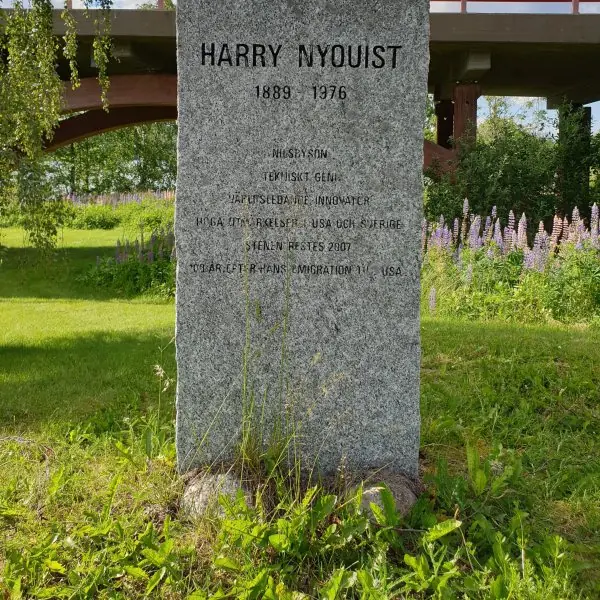
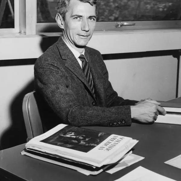
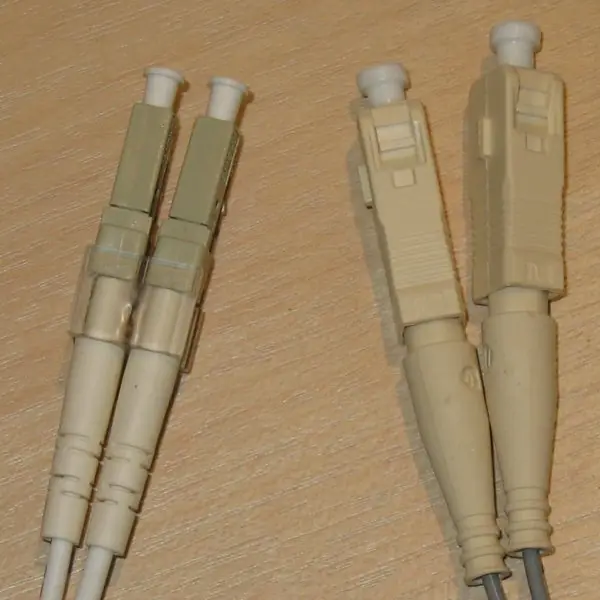
Plate 2.1 puts faces and cables side by side: the two engineers behind the two capacity formulas, a Cat5e cable with its four twisted pairs, and the LC and SC connectors of optical fibre.
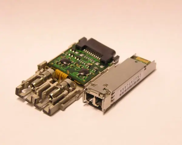
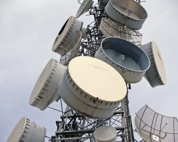
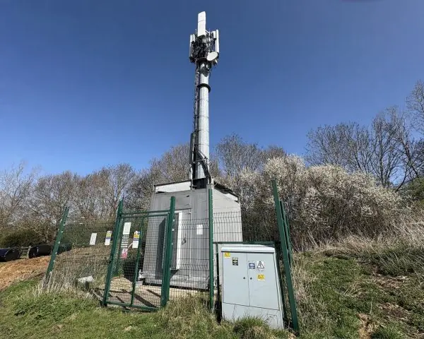
Plate 2.2 shows the boxes that turn bits into light and radio waves: an SFP optical transceiver, a tower of microwave dishes and a mobile base station.
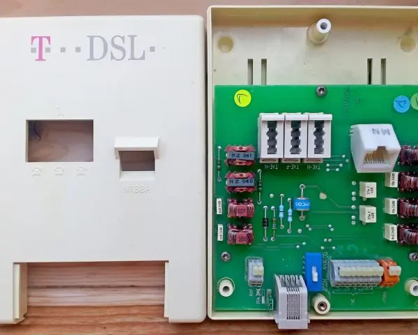
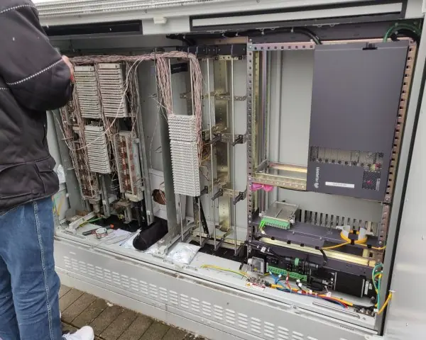
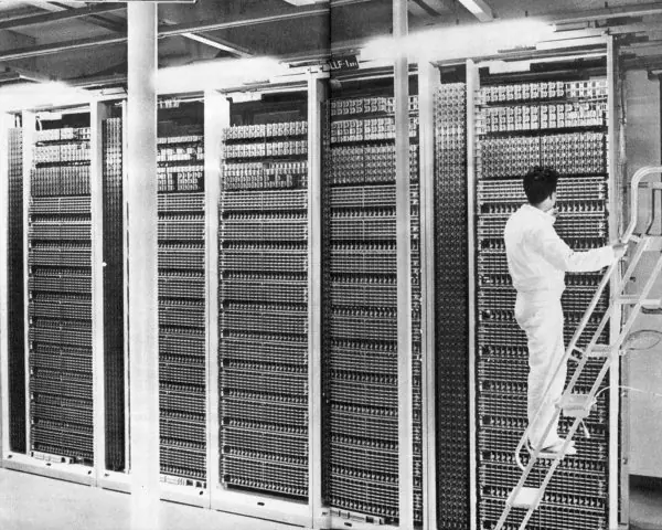
Plate 2.3 shows the telephone line at work: an ADSL splitter socket, an outdoor DSLAM cabinet and an old crossbar exchange.
The figures that follow are computed, not sketched: every capacity, waveform, delay and probability in them comes from the formulas of this unit.


2.9.1 Eight uses of physical-layer technology in Nepal
- Optical fibre backbones and fibre to the home. Internet providers such as WorldLink, Vianet and Subisu bring fibre to homes and offices in the valley and in big towns, and Nepal Telecom runs fibre between cities. Light in glass loses only 0.2 dB per kilometre, so a signal can travel tens of kilometres before it needs a repeater (Fig. 2.6). One fibre can be shared by 32 or 64 homes with a passive splitter, which keeps the cost per family low.
- Campus and office LANs on twisted pair. A college lab connects every computer to a switch with a Cat5e or Cat6 cable of at most 100 metres, wired to the T568B standard (Fig. 2.7). The twist of each pair cancels outside noise, so the cable is cheap and reliable (Plate 2.1c). When the cable run is longer than 100 metres, the right choice is to add a switch or use fibre.
- Microwave links to remote places. Where a road or a fibre trench is too costly, a pair of dishes on two hilltops can carry hundreds of megabits across tens of kilometres (Plate 2.2b). Hill-district health posts, schools and police posts are joined to the network this way. The two dishes must see each other, so the towers are built on ridges.
- Mobile data in every district. Nepal Telecom and Ncell cover towns and many villages with 4G cells, and each base station serves the phones in its cell (Plate 2.2c). The same set of radio channels is reused in cells that are far enough apart (Fig. 2.12), which lets millions of people use ConnectIPS, Fonepay and the Nagarik App at the same time. A phone that moves from one cell to the next is handed over without dropping the call.
- ADSL and VDSL on old telephone lines. In towns, a telephone pair can carry an Internet connection because ADSL uses frequencies above 25 kHz while voice stays below 4 kHz (Plate 2.3a). A DSLAM in the street cabinet puts many such lines on one fibre (Plate 2.3b). The speed falls as the copper gets longer, because the signal loses power and the SNR drops (Fig. 2.1).
- Satellite links for the hardest places. A VSAT dish can give a bank branch, an ATM or a remote school a connection where no cable and no mobile signal reaches. A geostationary link has a round trip of about 477 ms before any processing (Fig. 2.11), so it suits e-mail and payments better than voice calls or games. Low-orbit services reduce that delay to a few tens of milliseconds.
- Digital voice and E1 links. A telephone call is sampled 8000 times a second at 8 bits, giving 64 kbps (Fig. 2.5), and 30 such calls share one E1 line of 2.048 Mbps (Fig. 2.8). Mobile operators use E1 and larger multiplexed links to connect base stations to their exchanges. Knowing the frame structure explains why capacity is bought in units of 2 Mbps.
- Wi-Fi that adapts to the signal. A home router chooses a modulation to match the signal quality: 64-QAM or higher near the router, QPSK farther away (Fig. 2.4). This is Shannon's law at work, since a lower SNR means a lower capacity (Fig. 2.1). It is why the speed test next to the router is much better than the same test in the far bedroom.
Formula and fact sheet
- Nyquist: C = 2 B log₂ L. Shannon: C = B log₂(1 + SNR); SNR_dB = 10 log₁₀ SNR.
- Bit rate = baud × bits per signal element. PCM voice: 8000 × 8 = 64 kbps.
- T1 = 1.544 Mbps (24 channels), E1 = 2.048 Mbps (30 channels).
- Attenuation (dB) = 10 log₁₀(P₂/P₁); 3 dB ≈ factor 2 in power.
- Switching: circuit (reserve), message (store whole), packet (datagram or virtual circuit).
Chapter summary
- The physical layer moves raw bits as signals. Impairments are attenuation, distortion and noise.
- Nyquist limits a noiseless channel by bandwidth and levels; Shannon limits a noisy one by bandwidth and SNR.
- Line codes trade bandwidth against clock recovery: Manchester is self-clocking, NRZI and AMI are simpler.
- Fibre outperforms copper in bandwidth, distance and noise immunity; UTP dominates the last 100 m.
- Multiplexing shares a link by frequency, time or wavelength; switching shares a network by circuits or packets, and bursty data favours packets.
Practice
- Differentiate between baud rate and bit rate. A signal uses 8 levels at 2400 baud; find the bit rate.
- Find the Nyquist maximum bit rate of a 3000 Hz noiseless channel with 4 levels.
- Find the Shannon capacity of a 3000 Hz channel with SNR 30 dB.
- What is the minimum number of levels to carry 6 Mbps in a noiseless 1 MHz channel?
- Draw the Manchester and NRZI encodings of 10110010 (state your convention).
- Why is Manchester coding unsuitable for gigabit Ethernet? What replaces it?
- Compare UTP, coaxial and fibre for a campus backbone.
- Four channels of 8 bits per slot at 8000 frames/s are TDM-multiplexed. Find the link rate. What is T1's rate and why does it include one extra bit per frame?
- Compare circuit switching and packet switching with examples.
- Why is geostationary satellite delay too high for interactive games?
Answers and worked solutions
1. Baud = signal elements per second; bit rate = baud × bits per element. 8 levels = 3 bits, so 2400 × 3 = 7200 bps.
2. 2 × 3000 × log₂ 4 = 12,000 bps.
3. SNR = 1000, C = 3000 × log₂ 1001 ≈ 29,902 bps.
4. 2 × 10⁶ × log₂ L ≥ 6 × 10⁶, so log₂ L ≥ 3 and L = 8 (Shannon at 20 dB allows 6.66 Mbps, so it is feasible).
5. Manchester with 1 = low-to-high: 01 10 01 01 10 10 01 10. NRZI starting low with a flip on every 1: + + − + + + − −.
6. It needs twice the signal bandwidth of the bit rate (50 % efficiency), which is hard on copper at 1 Gbps; gigabit and faster Ethernet use 8B/10B, PAM-5 or 64B/66B block codes.
7. UTP: cheapest, 100 m limit, fine inside buildings. Coax: better shielded, older. Fibre: kilometres, huge bandwidth, no EMI; the right choice between buildings.
8. 4 × 8 × 8000 = 256,000 bps. T1: (24 × 8 + 1) × 8000 = 1,544,000 bps; the extra bit per frame is the framing bit used for frame synchronisation.
9. Circuit: reserved path, constant delay, wasted when idle (telephone). Packet: shared capacity, queuing delay, efficient for bursts (Internet).
10. The orbit is 35,786 km high; a one-way trip ground–satellite–ground takes about 240 ms, so a request and reply take about 480 ms plus processing, far above the 50 ms or so that games tolerate.
Model answers for Unit 2
Q1. State the Nyquist and Shannon limits on the data rate of a channel. Compute both for a telephone line and explain how they are used together. (10 marks)
Introduction. The data rate of a channel is not limited by the cleverness of the equipment but by physics. Two results set the limits: Nyquist's theorem for a channel without noise and Shannon's theorem for a channel with noise. Fig. 2.1 draws both for a 3000 Hz line.
Nyquist (noiseless channel). A channel of bandwidth B hertz can carry at most 2B signal elements per second without intersymbol interference (Fig. 2.2). If each element can take L levels, it carries log2 L bits, so the maximum bit rate is C = 2 B log2 L.
Shannon (noisy channel). Noise makes close levels impossible to tell apart (Fig. 2.4).
Shannon proved that the highest rate at which data can be sent with an arbitrarily small error is C = B log2(1 + SNR), where SNR is a power ratio, not decibels. A value in dB must first be converted: SNR = 10^{dB / 10}.
Worked example for B = 3000 Hz.
| Quantity | Calculation | Result |
|---|---|---|
| Nyquist, 2 levels | 2 x 3000 x log2 2 | 6000 bps |
| Nyquist, 4 levels | 2 x 3000 x log2 4 | 12 000 bps |
| Nyquist, 16 levels | 2 x 3000 x log2 16 | 24 000 bps |
| Shannon, SNR 30 dB (ratio 1000) | 3000 x log2 1001 | 29 902 bps |
How they are used together.
- Shannon gives the ceiling for the channel: 29.9 kbps for this line, whatever coding is used.
- Nyquist tells how many levels are needed for a target rate below the ceiling. For 24 kbps we need L = 16.
- The level count must be feasible at the SNR available. L levels need SNR of at least L squared minus 1: 3 for L = 2, 15 for L = 4 and 255 (24.07 dB) for L = 16.
- To increase the rate, increase B (a wider channel) or SNR (a cleaner line); doubling B doubles C, while doubling SNR adds only about B bits per second.
- A 56 kbps modem on a 3100 Hz line would need SNR of about 54 dB, which is why real lines gave less.
Conclusion. Nyquist limits a channel by its bandwidth and the number of levels, Shannon by its bandwidth and noise. Designers use Shannon to see whether a rate is possible at all, and Nyquist to choose the signalling scheme that reaches it.
Q2. What is line coding? Explain NRZ-L, NRZI, Manchester and AMI with the waveform of 10110010. (10 marks)
Introduction. Line coding converts digital data into a digital signal, a sequence of voltage levels, for transmission over a wire. A good code helps the receiver keep its clock, avoids a DC component, uses little bandwidth and, if possible, detects some errors.
Requirements of a good code.
- Synchronisation: the receiver has no separate clock wire, so it needs level changes in the data to stay in step.
- No DC component: a long-term average of zero lets transformers and capacitors in the link pass the signal.
- Low bandwidth: fewer changes per bit use less of the channel.
- Error detection: a rule that is broken by a single error, such as the alternation in AMI.
The four codes (Fig. 2.3).
| Code | Rule | Waveform for 10110010 | Strength | Weakness |
|---|---|---|---|---|
| NRZ-L | 1 is high, 0 is low | high, low, high, high, low, low, high, low | simple, uses least bandwidth | long runs of equal bits lose the clock |
| NRZI | a 1 flips the level, a 0 keeps it | + + - + + + - - (start low) | runs of 1s are safe | runs of 0s still lose the clock |
| Manchester | 1 is low then high, 0 is high then low | 01 10 01 01 10 10 01 10 | transition in every bit, self-clocking, no DC | needs twice the bandwidth |
| AMI | 0 is zero volts, 1s alternate +V and -V | + 0 - + 0 0 - 0 | no DC, single errors detected | long runs of 0s lose the clock |
Where they are used. Manchester coding was used by 10 Mbps Ethernet. Faster Ethernet avoids its 50 percent efficiency with block codes: 4B/5B (80 percent), 8B/10B and 64B/66B. AMI, with a scrambling rule, was used on T1 lines.
Checking the Manchester row. Take the bits 1, 0, 1, 1. Bit 1 becomes low-high (01), bit 0 becomes high-low (10), and the next two 1s become 01 and 01, so the line reads 01 10 01 01.
The signal changes level at least once in every bit period, even for the string 00000000, which is exactly what a receiver needs to stay locked.
The price is that the signal changes up to twice per bit, so a 10 Mbps stream needs about 20 MHz of bandwidth.
Conclusion. Line codes trade bandwidth against clock recovery. Manchester is the most robust but the most costly, NRZ-L the cheapest but the weakest in synchronisation, and the others sit between.
Q3. Compare the guided and unguided transmission media. Which medium would you choose for a college campus, and why? (10 marks)
Introduction. A transmission medium is the path that carries the signal.
Guided media (twisted pair, coaxial cable, optical fibre) keep the signal in a physical conductor; unguided media (radio, microwave, infrared, satellite) send it through the air. The choice depends on distance, speed, cost and noise.
Guided media.
- Twisted pair (UTP, STP). Pairs are twisted so that noise cancels (Plate 2.1c). Cat5e and Cat6 carry 1 Gbps up to 100 m and cost little.
- Coaxial cable. A copper core inside a braid shield resists noise better and was the bus of early Ethernet.
- Optical fibre. Light stays in the core by total internal reflection (Fig. 2.6). Fibre has very high bandwidth, loses 0.2 dB per km, is immune to electrical noise and cannot be tapped easily, but splicing needs skill (Plate 2.1d).
Unguided media. Radio waves cover people on the move (Wi-Fi, mobile networks); microwave dishes join towers on a straight line of sight (Plate 2.2b); satellites reach anywhere but with a long delay (Fig. 2.11).
| Medium | Typical reach | Speed | Cost | Noise immunity | Use |
|---|---|---|---|---|---|
| UTP Cat6 | 100 m | up to 10 Gbps (short runs) | low | fair | rooms, floors |
| Coaxial | 500 m | up to 1 Gbps (cable TV) | medium | good | cable broadband |
| Single-mode fibre | tens of km | 100 Gbps and more | high | excellent | backbone |
| Microwave | 30-50 km | 100 Mbps - 1 Gbps | medium | fair (weather) | hills, no fibre |
| Satellite | global | 10-300 Mbps | high | fair | remote areas |
Recommendation for a campus. Use fibre between buildings because the distance exceeds 100 m and lightning or earth-potential differences cannot travel along glass.
Use Cat6 UTP inside each building from a floor switch to the rooms, and Wi-Fi for mobile devices. A microwave link is only a backup.
Conclusion. There is no best medium, only the best medium for a distance and a budget. A campus uses a mixture: fibre for the backbone, copper for the last 100 metres and radio for convenience.
Q4. Explain frequency-division, time-division and wavelength-division multiplexing with examples. (5 marks)
Multiplexing lets many signals share one link. The link is divided in one of three ways.
- FDM gives each channel its own band of frequencies. Three 4 kHz voice channels with two 1 kHz guard bands need 3 x 4 + 2 x 1 = 14 kHz (Fig. 2.8). Radio, TV and the cable-TV network use FDM.
- TDM gives each channel the whole link for a short, fixed time slot in turn. One frame lasts 125 microseconds. A T1 frame has 24 slots of 8 bits plus 1 framing bit: 193 x 8000 = 1 544 000 bps. An E1 frame has 32 slots: 2 048 000 bps, of which 30 slots carry voice.
- WDM is FDM for light: each channel is a different colour of laser on the same fibre. Dense WDM carries 80 or more wavelengths, each at 100 Gbps.
- Statistical TDM gives a slot only to a channel that has data, which suits bursty traffic (Fig. 2.9).
For example, a voice call is exactly one slot of an E1 line (64 kbps), and the E1 line is one channel on a fibre that carries many colours.
Q5. Compare circuit switching and packet switching. Show with a calculation which is faster for a 9000 bit message over three links. (10 marks)
Introduction. A large network cannot join every pair of nodes directly, so intermediate nodes switch the data. The main methods are circuit switching, message switching and packet switching (datagram or virtual circuit).
Circuit switching. A dedicated path is set up for the call, used by it alone, and released at the end. The old telephone network works like this (Plate 2.3c).
Packet switching. The message is cut into packets, each with an address, and every node stores a packet and forwards it. Capacity is shared on demand. The Internet works like this.
Calculation (Fig. 2.10). Take a 9000 bit message, three links of 1 Mbps and no propagation delay.
- Message switching: each link must send all 9000 bits before the next starts: 3 x 9 = 27 ms.
- Packet switching: three packets of 3000 bits (3 ms each) pipeline through the links: (3 + 3 - 1) x 3 = 15 ms.
- Circuit switching: a 6 ms set-up, then 9 ms on all links at once = 15 ms, but the circuit is reserved for the whole time.
Comparison.
| Point | Circuit switching | Packet switching |
|---|---|---|
| Set-up | needed before data | none (datagram) |
| Path | fixed for the call | may change per packet |
| Capacity | reserved, wasted when idle | shared, used on demand |
| Delay | constant after set-up | varies with queues |
| Failure | call is lost if a node fails | packets take another route |
| Best for | steady voice | bursty data |
Statistical gain. If 35 users each need 100 kbps for 10 percent of the time on a 1 Mbps link, circuit switching serves 10 users but packet switching serves all 35 and overloads the link only 0.04 percent of the time (Fig. 2.9).
Virtual circuits. A third style sits between the two: a virtual circuit sets up a route once, then sends packets along it with a short circuit number instead of a full address, as MPLS does in an ISP core.
It keeps packet order and gives a predictable route without reserving the capacity of the links.
Conclusion. Circuit switching guarantees quality but wastes capacity. Packet switching uses capacity well and survives faults, at the price of variable delay. This is why the Internet is packet switched.
Q6. Explain pulse code modulation. How is the 64 kbps rate of a voice channel obtained? (5 marks)
PCM converts an analog voice signal into a digital one in three steps (Fig. 2.5).
- Sampling. Voice is limited to about 4 kHz. By Nyquist's sampling theorem it must be sampled at twice the highest frequency: 2 x 4000 = 8000 samples per second, one every 125 microseconds.
- Quantisation. Each sample is rounded to the nearest of 2^{n} levels. The rounding error is quantisation noise, and each extra bit adds about 6 dB to the SNR (8 bits give about 49.9 dB).
- Encoding. Each level is sent as an n-bit code word.
With 8 bits per sample the bit rate is 8000 x 8 = 64 000 bps, the DS0 channel. Thirty-two such channels fill the 2.048 Mbps E1 frame (Fig. 2.8).
The quality of the received voice depends on the number of bits: 3 bits would sound harsh, 8 bits sound natural.
In practice the levels are spaced non-uniformly (A-law in Europe and Nepal, mu-law in North America) so that quiet sounds are described more finely than loud ones.
Q7. Explain the cellular concept and frequency reuse. (5 marks)
A mobile network divides its area into cells, each served by a base station with a low-power transmitter (Plate 2.2c). Because power is low, a frequency used in one cell can be used again in another cell far enough away.
- Cluster. The available channels are split into N groups (commonly 7) and a cluster of N neighbouring cells uses each group once, with no two adjacent cells sharing a group (Fig. 2.12).
- Reuse distance. The nearest cell with the same group is at D = R x \sqrt{3N}; for N = 7 this is 4.58 R, which keeps co-channel interference low.
- Capacity gain. With 70 channels and N = 7, each cell has 10, but a city of 49 cells carries 490 calls at once, seven times the 70 calls possible without reuse.
- Handoff. When a phone moves toward the cell edge and the signal falls, the network switches the call to the next base station without a break.
- Trade-off. A smaller N gives more channels per cell but a smaller D and more interference; a smaller cell radius gives more capacity per area but needs more towers.
This is how Nepal Telecom and Ncell serve millions of subscribers with a limited share of the radio spectrum.