Unit 6 · 4 teaching hours · 23 min read
Input/Output Device Management
What the syllabus asks for 5
- Principles of I/O hardware
- Principles of I/O software
- I/O software layers
- Disk hardware and disk scheduling
- Seeing the ideas: interrupt controllers, disks and head movement
Disks, keyboards, printers and network cards differ wildly in speed (a keyboard sends a few bytes a second, a disk hundreds of megabytes).
The OS hides these differences behind a uniform interface and uses clever tricks (interrupts, DMA, buffering, disk scheduling) so that the CPU is not left waiting.
- I/O hardware: devices, controllers, memory-mapped I/O, DMA.
- I/O software: goals, programmed I/O, interrupt-driven I/O, DMA I/O, and the software layers.
- Disk hardware and disk scheduling (FCFS, SSTF, SCAN, C-SCAN, LOOK, C-LOOK) with verified examples.
6.1 Principles of I/O hardware
I/O devices
| Class | Transfer unit | Examples |
|---|---|---|
| Block devices | fixed-size blocks, randomly addressable | hard disk, SSD, USB drive |
| Character devices | stream of bytes, no addressing | keyboard, mouse, serial port, printer |
| Network devices | packets | Ethernet, Wi-Fi |
Data rates range over about nine orders of magnitude: keyboard ≈ 10 B/s; Gigabit Ethernet ≈ 125 MB/s; NVMe SSD ≈ several GB/s.
Device controllers
An I/O device has a mechanical part and an electronic part, the controller (adapter). The OS talks to the controller, not the device.
For a disk, the controller reads the bit stream, assembles it into a block, checks the error-correcting code and puts the block in its own buffer. The controller has registers (command, status, data) which the CPU reads and writes.
Addressing the controller: port-mapped and memory-mapped I/O
- Separate I/O space: each controller register has an I/O port number, accessed with special instructions (
IN,OUTon x86). - Memory-mapped I/O: the registers are mapped to addresses in the normal memory space, so ordinary
loadandstoreinstructions (and C pointers) control devices. No special instructions, and the OS can use page protection to decide who may touch a device; the cost is that caching must be disabled for those addresses.
Direct memory access (DMA)
Without DMA the CPU copies every byte between the controller and memory. A DMA controller moves a whole block by itself:
- The CPU programs the DMA controller: memory address, byte count, direction, device.
- The DMA controller requests the block from the device controller.
- The device controller transfers data to memory over the bus. (Cycle stealing: DMA takes bus cycles when the CPU is not using them.)
- On completion the device controller signals the DMA controller, which raises one interrupt to tell the CPU.
The CPU is therefore interrupted once per block instead of once per byte.
Reading a 4 KB block with interrupt-driven byte transfer needs 4,096 interrupts. If each interrupt costs 2 µs of CPU time, the CPU spends 8.2 ms servicing the transfer. With DMA there is one interrupt (2 µs), a saving of 99.98 %.
6.2 Principles of I/O software
Goals
- Device independence: programs read a file whether it is on a disk or a USB drive.
- Uniform naming: a name is a string, not tied to hardware (
/dev/sda,D:). - Error handling: handle errors as close to the hardware as possible; hide transient errors from higher layers.
- Synchronous (blocking) vs asynchronous (interrupt-driven) transfers: programs prefer blocking calls, hardware is interrupt-driven.
- Buffering: store data temporarily to smooth speed differences.
- Sharable vs dedicated devices: a disk is shared; a printer is exclusive (spooling resolves this).
Three ways to do I/O
| Method | How | CPU involvement | Good for |
|---|---|---|---|
| Programmed I/O (polling) | CPU loops reading the status register until ready, then copies each byte | 100 % busy during transfer | tiny embedded systems |
| Interrupt-driven I/O | CPU starts the device and does other work; device interrupts when a byte or block is ready | an interrupt per unit | slow character devices |
| I/O using DMA | DMA controller moves the block; one interrupt at the end | start + one interrupt | disks, network, bulk data |
To print "ABC" the CPU copies the first character to the printer's data register, then busy-waits until the status register says "ready", copies the next one, and so on.
In interrupt-driven I/O, the CPU copies one character, blocks the calling process (the scheduler runs something else) and the printer's "ready" interrupt wakes the process to send the next character.
6.3 I/O software layers
I/O software is organised in four layers, from the hardware up:
| Layer | Job |
|---|---|
| 1. Interrupt handlers | save registers, find the source of the interrupt, run the handler, unblock the waiting driver, restore and return |
| 2. Device drivers | device-specific code that issues commands to the controller, supplied by the manufacturer, normally run in kernel mode |
| 3. Device-independent I/O software | uniform interface to drivers, naming, protection, buffering, block size, allocation of dedicated devices, error reporting |
| 4. User-space I/O software | library calls (printf, read) and spooling daemons |
A typical interrupt sequence: the device raises the interrupt; the CPU saves the program counter and PSW and jumps to the handler; the handler acknowledges the interrupt controller, runs, and signals the driver; the scheduler picks the next process.
Buffering schemes: none (the process waits on every transfer), single buffer, double buffer (fill one while the process drains the other), circular buffer.
Spooling keeps a queue of print jobs on disk, and a daemon prints them one at a time, so processes need never hold the printer.
6.4 Disk hardware and disk scheduling
Disk geometry
A magnetic disk has platters with tracks divided into sectors; the same track on all platters forms a cylinder. The disk arm moves the heads to a cylinder.
A disk access has three parts:
- Seek time: moving the arm to the right cylinder (several ms).
- Rotational delay (latency): waiting for the sector to rotate under the head; average half a rotation.
- Transfer time: reading the data as it passes under the head.
Disk: 7200 rpm, average seek 9 ms, transfer rate 100 MB/s. One rotation takes 60/7200 = 8.33 ms, so the average rotational latency is half of it, 4.17 ms. Transfer of 4 KB = 4/1024 MB ÷ 100 MB/s = 0.039 ms.
Total ≈ 9 + 4.17 + 0.04 = 13.21 ms. Seek and rotation dominate, which is why scheduling the arm (and reading in large chunks) pays.
A track holding 400 sectors of 512 B turns 120 times per second, a media rate of 400 × 512 × 120 = 24.6 MB/s.
Seek time is the cost to minimise by ordering the requests. (SSDs have no arm, so these algorithms matter for hard disks; SSD schedulers mostly merge and batch requests.)
Disk scheduling algorithms
Take a disk with cylinders 0–199, the head at 53, and the queue of requests 98, 183, 37, 122, 14, 124, 65, 67. We count the total head movement in cylinders. All results below were computed by bca/tools/check_os.py.
FCFS. Serve in arrival order: 53 → 98 → 183 → 37 → 122 → 14 → 124 → 65 → 67. Movement: 45 + 85 + 146 + 85 + 108 + 110 + 59 + 2 = 640 cylinders. Fair, but a lot of wild swinging.
SSTF (shortest seek time first). Always go to the nearest pending request: 53 → 65 → 67 → 37 → 14 → 98 → 122 → 124 → 183. Movement: 12 + 2 + 30 + 23 + 84 + 24 + 2 + 59 = 236. A greedy choice like SJF; it can starve far-away requests when new nearby ones keep arriving.
SCAN (elevator). The arm sweeps in one direction, serving requests on the way, goes to the end of the disk, then reverses. Going up first: 53 → 65 → 67 → 98 → 122 → 124 → 183 → 199 → 37 → 14.
Movement: (199 − 53) + (199 − 14) = 146 + 185 = 331. If the arm instead started downwards: 53 → 37 → 14 → 0 → 65 → 67 → 98 → 122 → 124 → 183 gives 53 + 183 = 236. The direction at the start matters, so the question must state it.
LOOK. Like SCAN but reverses at the last request rather than the disk end: 53 → 65 → 67 → 98 → 122 → 124 → 183 → 37 → 14 = (183 − 53) + (183 − 14) = 130 + 169 = 299.
C-SCAN (circular SCAN). Sweeps in one direction only; at the end it jumps back to cylinder 0 without serving requests and starts again, giving more uniform waiting times. Path: 53 → 65 → 67 → 98 → 122 → 124 → 183 → 199 → 0 → 14 → 37.
Counting the return jump, movement is 146 + 199 + 37 = 382; if only the service sweeps are counted (the jump excluded) it is 146 + 37 = 183. Always say whether the return is counted.
C-LOOK. C-SCAN that goes only as far as the last request: 53 → 65 → 67 → 98 → 122 → 124 → 183 → 14 → 37: (183 − 53) + (183 − 14) + (37 − 14) = 130 + 169 + 23 = 322 (with the return jump counted).
| Algorithm | Total movement | Comment |
|---|---|---|
| FCFS | 640 | fair, worst here |
| SSTF | 236 | good average, starvation risk |
| SCAN (up first) | 331 | no starvation |
| SCAN (down first) | 236 | direction changes the answer |
| LOOK (up first) | 299 | SCAN without useless travel |
| C-SCAN (jump counted) | 382 | uniform wait |
| C-LOOK (jump counted) | 322 | C-SCAN without useless travel |
For light loads FCFS is acceptable; SSTF is a natural choice; under heavy load SCAN and C-SCAN are better because they cannot starve any request. Linux's historical elevators (deadline, CFQ, now mq-deadline and BFQ) are variants of these ideas.
Disk management and RAID in brief
Low-level formatting writes sectors with headers and ECC; the OS then partitions the disk and builds a file system. The boot block holds the bootstrap loader; bad blocks are remapped to spare sectors.
RAID combines disks: RAID 0 stripes for speed (no redundancy), RAID 1 mirrors, RAID 5 stripes with distributed parity (survives one disk failure; usable capacity (n − 1)/n).
6.5 Seeing the ideas: interrupt controllers, disks and head movement
Input and output is where the fast CPU meets slow machines.
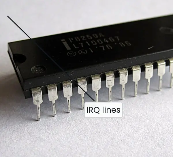
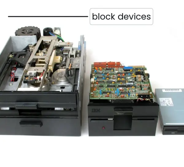
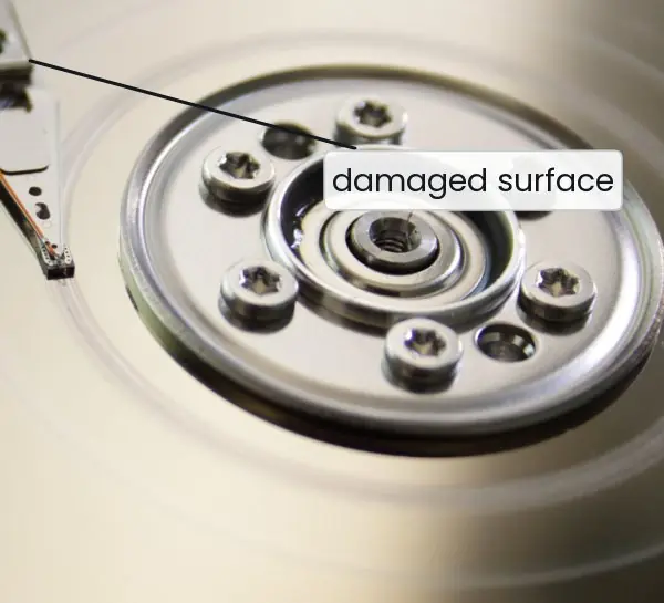
The plate shows three real components: the Intel 8259A chip that collects interrupt requests on the original PC, a set of floppy drives from three eras, and a hard-disk platter damaged by a head crash.
The figures follow one interrupt, compare programmed I/O with DMA, stack the I/O software layers and then draw the head movement of five disk-scheduling algorithms on the same request queue.


6.5.1 Eight advantages of buffering, spooling and device drivers
- Smoothing speed differences. A buffer holds data while a fast producer waits for a slow consumer. A song is read ahead from the disk so that playback does not stutter. The CPU and the device each work at their own pace.
- Matching block sizes. A program may write 10 bytes at a time while the disk accepts 512 or 4096 bytes. The OS collects the small writes in a buffer and sends full blocks. This reduces the number of slow disk operations.
- Caching repeated reads. A buffer cache keeps recently read disk blocks in memory. When the same file is opened again, it is served from RAM in nanoseconds instead of milliseconds. This is why a second launch of a program is faster than the first.
- Spooling shares one device. Print jobs from many users are saved on disk and sent to the printer one by one. No user waits for the printer or blocks the others. A cyber cafe with one laser printer relies on it.
- Uniform interface. Applications call the same read and write on a disk, a USB drive or a network socket. The OS hides the differences. A programmer does not need a new program for every device.
- Easy support for new hardware. Only the driver knows the controller's registers. A manufacturer ships a driver and the OS can use the device without any change to the kernel. This is how a new printer works after you install its driver.
- Protection and error handling. The OS checks every request before the driver is called and reports errors in a standard way. A user program cannot send raw commands to the disk controller. A failed read is retried or reported cleanly.
- Better CPU utilisation. With interrupts and DMA the CPU does other work while a device is busy. More processes make progress in the same time. Combined with scheduling, the system stays responsive during a large file copy.
Formula and fact sheet
- Access time = seek + rotational latency + transfer. Average latency = ½ × (60 / rpm) s.
- Transfer time = size / transfer rate. Media rate = sectors per track × sector size × rotations per second.
- FCFS, SSTF, SCAN, C-SCAN, LOOK, C-LOOK: total head movement in cylinders; state direction and whether jumps count.
- Programmed I/O = polling, interrupt-driven = per-unit interrupt, DMA = one interrupt per block.
- Layers: interrupt handlers → device drivers → device-independent software → user-space.
Chapter summary
- Devices are block or character; each has a controller reached through ports or memory-mapped registers.
- DMA lets the controller move whole blocks and interrupt the CPU once.
- I/O software aims for device independence, uniform naming, buffering and error handling; it is layered (handler, driver, device-independent, user).
- Disk time is dominated by seek and rotation, so the arm is scheduled: SSTF is greedy, SCAN and C-SCAN sweep, LOOK variants save needless travel.
Practice
- Differentiate block and character devices with two examples each.
- What is memory-mapped I/O? State one advantage and one disadvantage.
- Explain how DMA transfers a block, and why it reduces CPU load.
- Compare programmed, interrupt-driven and DMA I/O.
- List the four layers of I/O software and what each does.
- Disk at 5400 rpm, average seek 12 ms, transfer rate 80 MB/s. Find the average time to read one 8 KB block.
- Head at 50 on a disk with cylinders 0–199; queue 82, 170, 43, 140, 24, 16, 190. Compute total head movement for FCFS, SSTF and SCAN (up first).
- Why can SSTF starve requests, and how does SCAN avoid it?
- What is spooling? Name a device where it is used.
Answers and worked solutions
1. Block: hard disk, SSD (addressable fixed blocks). Character: keyboard, serial port (byte streams, no seek).
2. The device registers occupy part of the address space and are accessed with load/store. Advantages: no special I/O instructions, easy protection through memory management. Disadvantage: caching must be disabled for those addresses, and the bus must route addresses to memory or devices.
3. The CPU gives the DMA controller the memory address, count and direction; the controller moves the data over the bus without the CPU, then interrupts once. One interrupt per block instead of one per byte frees the CPU for other processes.
4. Programmed: CPU polls, 100 % busy. Interrupt-driven: CPU does other work, one interrupt per byte/word. DMA: one interrupt per block, best for large transfers.
5. Interrupt handlers (take the interrupt, wake the driver); device drivers (device-specific commands); device-independent software (naming, buffering, protection, errors); user-space (libraries, spooler).
6. One rotation = 60/5400 = 11.11 ms; average latency = 5.56 ms. Transfer = 8/1024 MB ÷ 80 MB/s = 0.098 ms. Total = 12 + 5.56 + 0.10 = 17.65 ms.
7. FCFS: |50−82| + |82−170| + |170−43| + |43−140| + |140−24| + |24−16| + |16−190| = 32 + 88 + 127 + 97 + 116 + 8 + 174 = 642. SSTF: 50 → 43 (7) → 24 (19) → 16 (8) → 82 (66) → 140 (58) → 170 (30) → 190 (20) = 208. SCAN up: 50 → 82 → 140 → 170 → 190 → 199, then to 43, 24, 16: (199 − 50) + (199 − 16) = 149 + 183 = 332.
8. If requests keep arriving near the head, the distant request is never the closest and waits indefinitely. SCAN guarantees that the arm eventually reaches every cylinder in a sweep, so every request waits at most about two sweeps.
9. Spooling stores output jobs in a disk queue and a daemon feeds the device one at a time, so no process holds a dedicated device. Used for printers.
Model answers (5 and 10 marks)
Q1. Explain the three techniques of performing I/O: programmed I/O, interrupt-driven I/O and DMA. (5 marks)
Programmed I/O (polling). The CPU starts the operation and then repeatedly tests the device's status register until it is ready, copying each byte itself. It is simple but wastes the CPU in a busy-waiting loop and is used only for very fast or simple devices.
Interrupt-driven I/O. The CPU starts the operation and continues with another process.
When the device is ready it raises an interrupt; the CPU saves its state, uses the interrupt vector to reach the handler, transfers the data and returns (Figure 6.1).
Waiting is eliminated, but the CPU still copies every byte and takes one interrupt per byte or word.
Direct memory access (DMA). The CPU programs a DMA controller with the memory address, the count and the direction. The controller moves the whole block between the device and memory without the CPU and interrupts once at the end (Figure 6.2).
| Technique | CPU involvement | Interrupts for a 4 KB block | Suitable for |
|---|---|---|---|
| Programmed | copies all and waits | none (polling) | simple devices |
| Interrupt-driven | copies all, does not wait | up to 4096 | keyboards, mice |
| DMA | sets up only | 1 | disks, network cards |
DMA is the best for block devices because it frees the CPU for useful work.
Q2. What is a device driver? Explain the layers of I/O software. (5 marks)
A device driver is a device-specific module of the OS that knows how to operate one type of controller: it writes commands to the controller's registers, handles its status and translates the generic request into device actions.
Drivers are written by the manufacturer and loaded into the kernel.
The I/O software is arranged in four layers above the hardware (Figure 6.3):
- Interrupt handlers at the bottom: they run when a device finishes and wake the blocked driver.
- Device drivers: the only device-dependent layer; each driver serves one device or class.
- Device-independent software: naming (such as /dev/sda), protection, buffering, error reporting, allocation of dedicated devices and a uniform interface to the drivers.
- User-level software: library calls like
printfand spooling programs.
A request goes down through the layers and the result comes back up. The design lets the OS support thousands of devices behind one read and write interface, because a new device needs only a new driver.
Q3. Explain the disk scheduling algorithms FCFS, SSTF, SCAN, C-SCAN and LOOK. For the queue 98, 183, 37, 122, 14, 124, 65, 67 with the head at 53 on a disk of 200 cylinders, find the total head movement. (10 marks)
Introduction. Disk access time is mostly seek time, the movement of the arm to the right cylinder. The scheduler reorders pending requests to reduce the total head movement. The five algorithms are compared on the same queue in Figure 6.4.
FCFS serves requests in arrival order. It is fair but the head moves widely: 53 to 98 (45), to 183 (85), to 37 (146), to 122 (85), to 14 (108), to 124 (110), to 65 (59), to 67 (2) gives 640 cylinders.
SSTF (shortest seek time first) always goes to the nearest request: 53, 65, 67, 37, 14, 98, 122, 124, 183, total 12 + 2 + 30 + 23 + 84 + 24 + 2 + 59 = 236. It is efficient but can starve distant requests.
SCAN (elevator) sweeps the head in one direction to the end of the disk, serving requests on the way, and then reverses. Moving toward 0 first: 53 to 0 is 53, then 0 to 183 is 183, total 236.
C-SCAN sweeps in one direction only; at the end the head returns to the other end without serving and starts again. Going up: 53 to 199 is 146, jump to 0 is 199, then 0 to 37 is 37, total 382 (including the return jump). It gives a more uniform waiting time.
LOOK is SCAN that turns around at the last request instead of the disk edge: 53 to 14 is 39, then 14 to 183 is 169, total 208.
| Algorithm | Total head movement | Remark |
|---|---|---|
| FCFS | 640 | fair, slow |
| SSTF | 236 | may starve |
| SCAN | 236 | elevator, no starvation |
| C-SCAN | 382 | uniform wait |
| LOOK | 208 | best here |
Conclusion. LOOK has the least movement for this queue, 208 against 640 for FCFS. Real systems use LOOK or C-LOOK variants, and on SSDs, which have no moving arm, simple scheduling is enough.
Q4. Differentiate between buffering, caching and spooling. (5 marks)
Buffering keeps data in memory temporarily while it moves between two parties of different speeds or block sizes, for example a keyboard buffer or the buffer in which a video player collects frames. The data is usually read once and the buffer may hold the only copy.
Caching keeps a copy of data that is stored elsewhere, in faster memory, to speed up repeated access. A disk cache holds recently used blocks so that a second read is served from RAM; the original stays on disk.
Spooling (simultaneous peripheral operations on-line) stores the output for a device that cannot interleave requests, such as a printer, on disk until the device is free. Jobs print one after another without blocking the users.
| Point | Buffering | Caching | Spooling |
|---|---|---|---|
| Purpose | speed matching | faster repeated access | share a non-shareable device |
| Holds | the data in transit | copy of data | whole jobs on disk |
| Example | video buffer | disk cache | print queue |
Q5. A disk rotates at 7200 rpm, the average seek time is 9 ms and the transfer rate is 100 MB per second. Find the average time to read a 4 KB block. (5 marks)
Access time = seek time + rotational latency + transfer time.
- Seek time is given: 9 ms.
- Rotational latency. At 7200 rpm one rotation takes 60 / 7200 = 8.333 ms. On average the wanted sector is half a rotation away, so the latency is 8.333 / 2 = 4.167 ms.
- Transfer time = 4096 bytes / 100,000,000 bytes per second = 0.0410 ms.
Total = 9 + 4.167 + 0.041 = 13.21 ms.
The result shows that seek and rotation, the mechanical parts, take more than 99 percent of the time and the transfer only 0.3 percent.
This is why the OS uses disk scheduling to cut seek time, reads whole blocks and uses a buffer cache. An SSD has no seek or rotation, so its access time is about 0.1 ms.