Unit 2 · 39 min read
8085 Instruction Set and Assembly Programming
What the syllabus asks for 7
- Instruction format and addressing modes
- The instruction groups
- Writing a program
- Counters and time-delay routines
- The stack and subroutines
- Interfacing concepts
- Seeing the ideas: opcodes, addressing modes, loops, delays and the stack
An instruction set is the vocabulary of the machine. In this unit you learn the 8085's addressing modes and instruction groups, then write real programs: arithmetic, loops over arrays, delays, subroutines, and the idea of interfacing.
Every program in this unit was assembled and executed on the book's 8085 simulator (tools/check_mpca.py) with the test data shown; the hex listings are the assembler's output.
- Instruction format, opcode and operand, addressing modes.
- The instruction groups with exact meaning and flags affected.
- Fifteen complete programs with machine code, test data and results.
- Counters, time-delay loops with the T-state formula, stack and subroutines.
- Interfacing concepts: memory-mapped and I/O-mapped I/O, address decoding, the 8255.
2.1 Instruction format and addressing modes
An instruction has an opcode (what to do) and zero to two operand bytes (what to do it to).
Instructions are 1, 2 or 3 bytes long: the first byte is always the opcode; a 2-byte instruction carries an 8-bit datum or port; a 3-byte one carries a 16-bit datum or address, stored low byte first (little-endian).
MVI A,32H   → 3E 32             (2 bytes)
LDA 2050H   → 3A 50 20          (3 bytes; address 2050H stored as 50, 20)
| Mode | Where the operand is | Example |
|---|---|---|
| Immediate | in the instruction itself | MVI B,05H, LXI H,2050H |
| Register | in a CPU register | MOV A,B, ADD C |
| Direct | at the 16-bit address in the instruction | LDA 2050H, STA 2052H, IN 80H |
| Register indirect | at the address held in a register pair | MOV A,M, LDAX B, LDAX D |
| Implied (implicit) | the instruction names it by its nature | CMA, RAL, STC (operand is A or a flag) |
2.2 The instruction groups
Data transfer (no flags affected)
| Instruction | Operation |
|---|---|
MOV Rd,Rs |
copy register to register (either may be M) |
MVI R,d8 |
load 8-bit immediate into R (or M) |
LXI rp,d16 |
load 16-bit immediate into BC, DE, HL or SP |
LDA a16 / STA a16 |
load/store A from/to a direct address |
LHLD a16 / SHLD a16 |
load/store L from a16 and H from a16+1 (and back) |
LDAX B/D / STAX B/D |
A ↔ memory addressed by BC or DE |
XCHG |
swap HL with DE |
Arithmetic
| Instruction | Operation | Flags |
|---|---|---|
ADD R, ADI d8 |
A ← A + R (or immediate) | all five |
ADC R, ACI d8 |
A ← A + R + CY | all five |
SUB R, SUI d8 |
A ← A − R | all five (CY = borrow) |
SBB R, SBI d8 |
A ← A − R − CY | all five |
INR R / DCR R |
R ← R ± 1 | all except CY |
INX rp / DCX rp |
16-bit pair ± 1 | none |
DAD rp |
HL ← HL + rp | only CY |
DAA |
decimal-adjust A after a BCD addition | all five |
Logical and compare
| Instruction | Operation | Notes |
|---|---|---|
ANA R, ANI d8 |
A ← A AND R | CY = 0, AC = 1 |
ORA R, ORI d8 |
A ← A OR R | CY = AC = 0; ORA A tests A for zero |
XRA R, XRI d8 |
A ← A XOR R | CY = AC = 0; XRA A clears A |
CMP R, CPI d8 |
compute A − R, set flags, discard the result | Z = 1 if equal; CY = 1 if A < R |
CMA |
complement A (1's complement) | no flags |
RLC / RRC |
rotate A left/right; the bit shifted out also goes to CY | only CY |
RAL / RAR |
rotate A through the carry (9-bit rotate) | only CY |
STC / CMC |
set / complement carry | CY |
Branching
| Instruction | Condition |
|---|---|
JMP a16 |
always |
JZ / JNZ |
Z = 1 / Z = 0 |
JC / JNC |
CY = 1 / CY = 0 |
JP / JM |
S = 0 (plus) / S = 1 (minus) |
JPE / JPO |
P = 1 (even) / P = 0 (odd) |
CALL a16, RET |
call a subroutine (push return address) / return (pop it) |
PCHL |
PC ← HL (jump through a register) |
Stack, I/O and machine control
PUSH rp / POP rp (rp = BC, DE, HL or PSW = A + flags), XTHL, SPHL, IN p8, OUT p8, EI, DI, RIM, SIM, NOP (does nothing, 4 T), HLT (stop until reset or interrupt).
- Operand order:
MOV B,Acopies A into B (destination first). - Compare, don't subtract, when you must keep A:
CMP/CPIleave A unchanged. - INX/DCX change no flags: testing a 16-bit counter for zero needs
MOV A,H ; ORA L ; JNZ— the Z flag afterDCX Hmeans nothing. - Data transfer does not affect flags: do not test a flag set by an
ADDafter intervening MOV…MVI.
2.3 Writing a program
Assembly code is written in mnemonics, then assembled to machine code in hex and loaded into RAM. On a trainer kit you key in the hex starting at, say, 2000H and run. The programs here start at 2000H; data is at 2050H upward.
A program is: initialise → loop (body, update pointer, update counter, test) → store result → HLT.
Program 1 — Add two 8-bit numbers (with carry)
Data: 2050H = F5H, 2051H = 1BH. Result: sum in 2052H, carry in 2053H.
2000  3A 50 20   LDA 2050H     ; A = first number
2003  47         MOV B,A       ; B = first
2004  3A 51 20   LDA 2051H     ; A = second
2007  80         ADD B         ; A = A + B, CY = carry
2008  32 52 20   STA 2052H     ; store sum (STA does not disturb CY)
200B  3E 00      MVI A,00H     ; MVI does not disturb CY either
200D  8F         ADC A         ; A = 0 + 0 + CY = the carry bit
200E  32 53 20   STA 2053H     ; store carry
2011  76         HLT
Result (run on the simulator): F5H + 1BH = 110H → 2052H = 10H, 2053H = 01H. Test 23H + 14H gives 37H, carry 0. The trick ADC A after clearing A is the standard way to turn CY into a byte.
Program 2 — Add two 16-bit numbers
Data: 2050H–2051H = 45F3H (low byte first: F3, 45), 2052H–2053H = FA1EH. Result at 2054H–2055H, carry at 2056H.
2000  2A 50 20   LHLD 2050H    ; HL = first
2003  EB         XCHG          ; DE = first
2004  2A 52 20   LHLD 2052H    ; HL = second
2007  19         DAD D         ; HL = HL + DE, CY = carry out of bit 15
2008  22 54 20   SHLD 2054H    ; store sum
200B  3E 00      MVI A,00H
200D  8F         ADC A
200E  32 56 20   STA 2056H     ; carry
2011  76         HLT
Result: 45F3H + FA1EH = 14011H → 2054H–2055H = 4011H (stored 11, 40), carry = 1.
Program 3 — Subtract; report the sign
Data: 2050H = minuend, 2051H = subtrahend. Result magnitude in 2052H; 2053H = 0 if the answer is non-negative, 1 if negative.
2000  3A 50 20   LDA 2050H
2003  47         MOV B,A
2004  3A 51 20   LDA 2051H
2007  4F         MOV C,A
2008  78         MOV A,B
2009  91         SUB C         ; A = B - C; CY = 1 if borrow
200A  32 52 20   STA 2052H
200D  D2 1A 20   JNC DONE      ; no borrow: result is already correct
2010  2F         CMA           ; negative: two's complement to get magnitude
2011  3C         INR A
2012  32 52 20   STA 2052H
2015  3E 01      MVI A,01H     ; sign = 1
2017  C3 1C 20   JMP SAVE
201A  3E 00      MVI A,00H     ; DONE: sign = 0
201C  32 53 20   STA 2053H     ; SAVE
201F  76         HLT
Results: 4BH − 2CH → 1FH, sign 0. 2CH − 4BH → magnitude 1FH, sign 1.
Program 4 — 8-bit multiplication by repeated addition
Data: 2050H = multiplicand (C8H = 200), 2051H = multiplier (0AH = 10). Result: 16-bit product at 2052H–2053H.
2000  3A 50 20   LDA 2050H
2003  5F         MOV E,A       ; DE = multiplicand (16-bit, D = 0)
2004  16 00      MVI D,00H
2006  3A 51 20   LDA 2051H
2009  4F         MOV C,A       ; C = multiplier = loop counter
200A  21 00 00   LXI H,0000H   ; HL = running product
200D  79         MOV A,C       ; if multiplier is 0 the product is 0
200E  B7         ORA A
200F  CA 17 20   JZ STORE
2012  19         DAD D         ; LOOP: HL = HL + multiplicand
2013  0D         DCR C
2014  C2 12 20   JNZ LOOP
2017  22 52 20   SHLD 2052H    ; STORE
201A  76         HLT
Results: C8H × 0AH = 07D0H (2000) → 2052H = D0H, 2053H = 07H. Also tested FFH × FFH = FE01H and 07H × 00H = 0000H. Repeated addition is simple but slow (the first run took 324 T-states; a 255-iteration run takes thousands).
Program 5 — Division by repeated subtraction
Data: 2050H = dividend (100), 2051H = divisor (7). Quotient at 2052H, remainder at 2053H.
2000  3A 50 20   LDA 2050H
2003  47         MOV B,A
2004  3A 51 20   LDA 2051H
2007  4F         MOV C,A       ; C = divisor
2008  16 00      MVI D,00H     ; D = quotient
200A  78         MOV A,B       ; A = dividend
200B  B9         CMP C         ; LOOP: A < C ?
200C  DA 14 20   JC DONE
200F  91         SUB C         ; A = A - C
2010  14         INR D         ; quotient + 1
2011  C3 0B 20   JMP LOOP
2014  32 53 20   STA 2053H     ; DONE: A = remainder
2017  7A         MOV A,D
2018  32 52 20   STA 2052H
201B  76         HLT
Result: 100 ÷ 7 → quotient 14 (0EH), remainder 2. (The divisor must be non-zero — dividing by zero here would loop 256 times and produce nonsense; a robust program tests it first.)
Program 6 — Largest number in an array
Data: 2050H = count N, then N bytes from 2051H. Result at 2060H. Test array: 25, 9C, 41, F0, 08, 7E.
2000  3A 50 20   LDA 2050H
2003  4F         MOV C,A       ; C = count
2004  21 51 20   LXI H,2051H   ; HL points to the first element
2007  7E         MOV A,M       ; A = first element = current maximum
2008  0D         DCR C         ; one element already used
2009  23         INX H         ; LOOP: next element
200A  BE         CMP M         ; compare A with M (A - M)
200B  D2 0F 20   JNC SKIP      ; CY = 0: A >= M, keep A
200E  7E         MOV A,M       ; else A = M (new maximum)
200F  0D         DCR C         ; SKIP
2010  C2 09 20   JNZ LOOP
2013  32 60 20   STA 2060H
2016  76         HLT
Result: F0H. For the smallest number, change JNC SKIP to JC SKIP (the program was run both ways: smallest = 08H). Note CMP leaves A intact — that is what makes it right for this job.
Program 7 — Sum of a series (16-bit result)
Data: 2050H = N, bytes from 2051H. Result: low byte 2060H, high byte 2061H. Test: F0, F0, 80, 33, 0A (sum 1F3H).
2000  3A 50 20   LDA 2050H
2003  4F         MOV C,A
2004  21 51 20   LXI H,2051H
2007  3E 00      MVI A,00H     ; A = sum (low)
2009  06 00      MVI B,00H     ; B = sum (high)
200B  86         ADD M         ; LOOP
200C  D2 10 20   JNC NEXT
200F  04         INR B         ; carry: bump the high byte
2010  23         INX H         ; NEXT
2011  0D         DCR C
2012  C2 0B 20   JNZ LOOP
2015  32 60 20   STA 2060H
2018  78         MOV A,B
2019  32 61 20   STA 2061H
201C  76         HLT
Result: 0x01F3 → 2060H = F3H, 2061H = 01H. (INR B does not alter CY — which is why it is safe inside the loop.)
Program 8 — Block transfer
Move N bytes from 2051H… to 3051H… Result: the same bytes at the destination.
2000  3A 50 20   LDA 2050H
2003  4F         MOV C,A       ; count
2004  21 51 20   LXI H,2051H   ; source pointer
2007  11 51 30   LXI D,3051H   ; destination pointer
200A  7E         MOV A,M       ; LOOP
200B  12         STAX D
200C  23         INX H
200D  13         INX D
200E  0D         DCR C
200F  C2 0A 20   JNZ LOOP
2012  76         HLT
Tested with N = 5, bytes 1–5: all five appear at 3051H–3055H.
Program 9 — Count the 1-bits in a byte
Data: 2050H = B7H (1011 0111). Result at 2051H.
2000  3A 50 20   LDA 2050H
2003  06 00      MVI B,00H     ; B = count of ones
2005  0E 08      MVI C,08H     ; C = 8 bits
2007  1F         RAR           ; LOOP: bit 0 → CY
2008  D2 0C 20   JNC SKIP
200B  04         INR B
200C  0D         DCR C         ; SKIP
200D  C2 07 20   JNZ LOOP
2010  78         MOV A,B
2011  32 51 20   STA 2051H
2014  76         HLT
Result: 6 ones in B7H.
Program 10 — Two's complement of a 16-bit number
Data: 2050H–2051H = 1234H (34, 12). Result at 2052H–2053H = EDCCH.
2000  2A 50 20   LHLD 2050H
2003  7D         MOV A,L
2004  2F         CMA
2005  6F         MOV L,A
2006  7C         MOV A,H
2007  2F         CMA
2008  67         MOV H,A
2009  23         INX H         ; +1 : 16-bit, no flag trap
200A  22 52 20   SHLD 2052H
200D  76         HLT
Result: −1234H = EDCCH (verified: 1234H + EDCCH = 10000H).
Program 11 — BCD addition with DAA
Data: 2050H = 58, 2051H = 67 (packed BCD). Result: 2052H = tens/units, 2053H = hundreds.
2000  3A 50 20   LDA 2050H
2003  47         MOV B,A
2004  3A 51 20   LDA 2051H
2007  80         ADD B         ; binary add: 58H + 67H = BFH
2008  27         DAA           ; decimal adjust: BFH → 25H, CY = 1
2009  32 52 20   STA 2052H
200C  3E 00      MVI A,00H
200E  8F         ADC A         ; hundreds digit from the carry
200F  32 53 20   STA 2053H
2012  76         HLT
Result: 58 + 67 = 125 → 2053H = 01H, 2052H = 25H. (29 + 13 = 42: 2053H = 00H, 2052H = 42H.) DAA adds 06H to a low nibble > 9 (or AC = 1) and 60H to a high nibble > 9 (or CY = 1).
Program 12 — Sort ascending (bubble sort)
Data: N at 2050H, array from 2051H. Test: 25, 9C, 41, F0, 08, 7E → 08, 25, 41, 7E, 9C, F0.
2000  3A 50 20   LDA 2050H
2003  57         MOV D,A
2004  15         DCR D         ; D = N-1 passes
2005  21 51 20   LXI H,2051H   ; OUTER
2008  4A         MOV C,D       ; comparisons this pass
2009  7E         MOV A,M       ; INNER: A = a[i]
200A  23         INX H
200B  BE         CMP M         ; a[i] - a[i+1]
200C  DA 17 20   JC NOSWAP     ; a[i] < a[i+1]
200F  CA 17 20   JZ NOSWAP     ; equal
2012  46         MOV B,M       ; swap a[i], a[i+1]
2013  77         MOV M,A
2014  2B         DCX H
2015  70         MOV M,B
2016  23         INX H         ; undo DCX
2017  0D         DCR C         ; NOSWAP
2018  C2 09 20   JNZ INNER
201B  15         DCR D
201C  C2 05 20   JNZ OUTER
201F  76         HLT
Run on the test array it produced exactly the sorted list. It does at most (N − 1) passes of (N − 1 … 1) comparisons, i.e. O(N²).
Program 13 — Count the even numbers in an array
Even numbers have bit 0 = 0, so RRC moves bit 0 into CY.
2000  3A 50 20   LDA 2050H
2003  4F         MOV C,A
2004  21 51 20   LXI H,2051H
2007  06 00      MVI B,00H
2009  7E         MOV A,M       ; LOOP
200A  0F         RRC           ; bit 0 → CY
200B  DA 0F 20   JC ODD
200E  04         INR B         ; even
200F  23         INX H         ; ODD
2010  0D         DCR C
2011  C2 09 20   JNZ LOOP
2014  78         MOV A,B
2015  32 60 20   STA 2060H
2018  76         HLT
Test array 25, 9C, 41, F0, 08, 7E → 4 even numbers (9C, F0, 08, 7E).
2.4 Counters and time-delay routines
A counter is a register that is incremented or decremented in a loop, and its terminal value ends the loop (DCR C ; JNZ LOOP). Because every instruction takes a known number of T-states, a loop doing nothing useful makes a precise delay.
One-loop delay
        MVI B,count      ; 7 T
LOOP:   DCR B            ; 4 T
        JNZ LOOP         ; 10 T if taken, 7 T if not
The loop body costs 14 T per full pass; the last pass costs 11 (JNZ not taken). Total:
T = 7 + 14 (count − 1) + 11 = 14 × count + 4 T-states
The simulator confirms this for count = 1, 5 and FFH (3574 T for FFH).
1 ms = 3000 T-states at 3 MHz (T = 0.333 µs). 14n + 4 = 3000 ⇒ n = 214 = D6H.
Check 14 × 214 + 4 = 3000 T ⇒ exactly 1.000 ms. A single 8-bit counter gives at most 14 × 255 + 4 = 3574 T = 1.19 ms; for longer delays nest two loops, or use a 16-bit counter.
Nested (two-loop) delay
        MVI B,outer
OUT_:   MVI C,inner       ; 7 T
IN_:    DCR C             ; 4 T
        JNZ IN_           ; 10/7 T
        DCR B             ; 4 T
        JNZ OUT_          ; 10/7 T
One pass of the inner loop, including its MVI C, costs 7 + 14 (C − 1) + 11 = 14C + 4 T. The outer loop repeats that B times and adds DCR B (4 T) and JNZ (10 T taken, 7 T on the last pass):
T = 7 + B (14C + 4) + 14 (B − 1) + 11 = 14·B·C + 18·B + 4 T-states
Check with B = 2, C = 3: 14 × 6 + 36 + 4 = 124 T, which is exactly what the simulator counted. With B = C = FFH the delay is 14 × 65,025 + 18 × 255 + 4 = 914,944 T ≈ 0.305 s at 3 MHz — long enough to blink an LED visibly.
16-bit counter delay
        LXI D,count
LOOP:   DCX D             ; 6 T — sets no flags!
        MOV A,D           ; 4 T
        ORA E             ; 4 T  — Z = 1 only when DE = 0
        JNZ LOOP          ; 10/7 T
24 T per pass, so n = (delay in T) / 24.
2.5 The stack and subroutines
The stack is an area of RAM used last-in-first-out, addressed by SP. It grows downward: PUSH decrements SP twice and stores the pair (high byte at SP−1, low byte at SP−2); POP loads and increments SP twice. Always initialise SP (LXI SP,27FFH) before using the stack.
2000  31 FF 27   LXI SP,27FFH
2003  01 34 12   LXI B,1234H
2006  11 78 56   LXI D,5678H
2009  C5         PUSH B
200A  D5         PUSH D
200B  C1         POP B        ; B,C get what was pushed LAST (DE)
200C  D1         POP D
200D  76         HLT
After it, BC = 5678H and DE = 1234H: a push/pop pair in reverse order swaps the pairs (tested).
CALL and RET
CALL addr pushes the address of the next instruction (PC) on the stack and jumps; RET pops it back into PC.
2000  31 FF 27   LXI SP,27FFH
2003  3E 05      MVI A,05H
2005  CD 0C 20   CALL DOUBLE   ; pushes 2008H, jumps to 200CH
2008  32 50 20   STA 2050H     ; A = 0AH here
200B  76         HLT
200C  87         DOUBLE: ADD A ; A = A + A
200D  C9         RET           ; pops 2008H into PC
Result: 2050H = 0AH (tested). A subroutine saves registers it changes with PUSH/POP pairs, and the pushes must match the pops in reverse order, or RET will jump to garbage.
2.6 Interfacing concepts
Memory-mapped I/O and I/O-mapped I/O
| I/O-mapped (isolated) | Memory-mapped | |
|---|---|---|
| Instructions | only IN port / OUT port (A ↔ port) |
any memory instruction (LDA, MOV M,A, ADD M…) |
| Address | 8-bit port address (256 ports); copied onto both A0–A7 and A8–A15 | full 16-bit address |
| Control signal | IO/M' = 1 | IO/M' = 0 |
| Memory space | all 64 KB for memory | I/O devices take away some memory space |
| Decoding | simpler (8 lines) | needs 16-bit decoding |
| Speed/flexibility | A only | arithmetic directly on device registers |
Address decoding
A decoder such as the 74LS138 (3-to-8) turns the high address lines into one chip-select per device, so each memory chip or port occupies a unique block.
Example a 2 KB RAM (2K × 8) has 11 address lines (A0–A10) going to the chip; A11–A15 are decoded to form the select. To get a 64 KB map from 16 KB chips you need 4 chips and A14–A15 as 2 select lines (checked).
The 8255 programmable peripheral interface
A general-purpose parallel I/O chip with three 8-bit ports (A, B, C) and a control register, selected by A1, A0: 00 = port A, 01 = port B, 10 = port C, 11 = control. In I/O-mapped use with the chip at port addresses 80H–83H:
| Control word bit | Meaning |
|---|---|
| D7 = 1 | I/O mode (D7 = 0 is bit-set/reset mode for port C) |
| D6 D5 | group A mode (00 = mode 0, 01 = mode 1, 1x = mode 2) |
| D4 | port A: 1 = input, 0 = output |
| D3 | port C upper: 1 = input |
| D2 | group B mode (0 = mode 0, 1 = mode 1) |
| D1 | port B: 1 = input |
| D0 | port C lower: 1 = input |
2000  3E 80      MVI A,80H     ; control word: mode 0, all ports OUTPUT
2002  D3 83      OUT 83H       ; write control register
2004  3E 55      MVI A,55H
2006  D3 80      OUT 80H       ; 55H appears on port A pins (LEDs 01010101)
2008  76         HLT
Control words: 80H = all outputs; 90H = A input, B and C output; 9BH = all three ports input. (This short program was assembled by the book's assembler but not executed: the simulator has no ports. The control-word values are from the 8255 data sheet.)
2.7 Seeing the ideas: opcodes, addressing modes, loops, delays and the stack
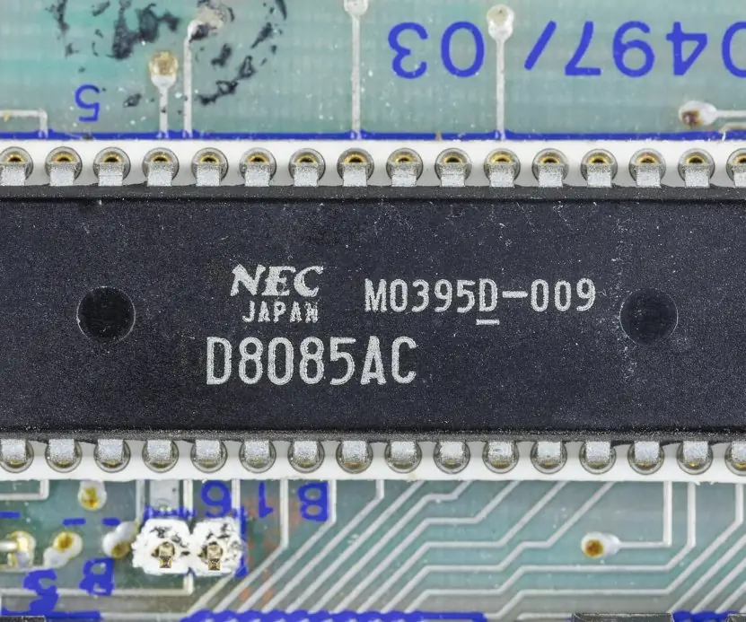
An assembly program is only a list of bytes in memory, and every instruction has a fixed size and time. The plate pairs the real 8085 die with the bit layout of an opcode.
The figures then show the five addressing modes, a trace of the largest-number program, the delay formula against real T-state counts, and the stack during PUSH, POP, CALL and RET.
All listings, results and T-state counts below come from the 8085 simulator in bca/tools/check_mpca.py.
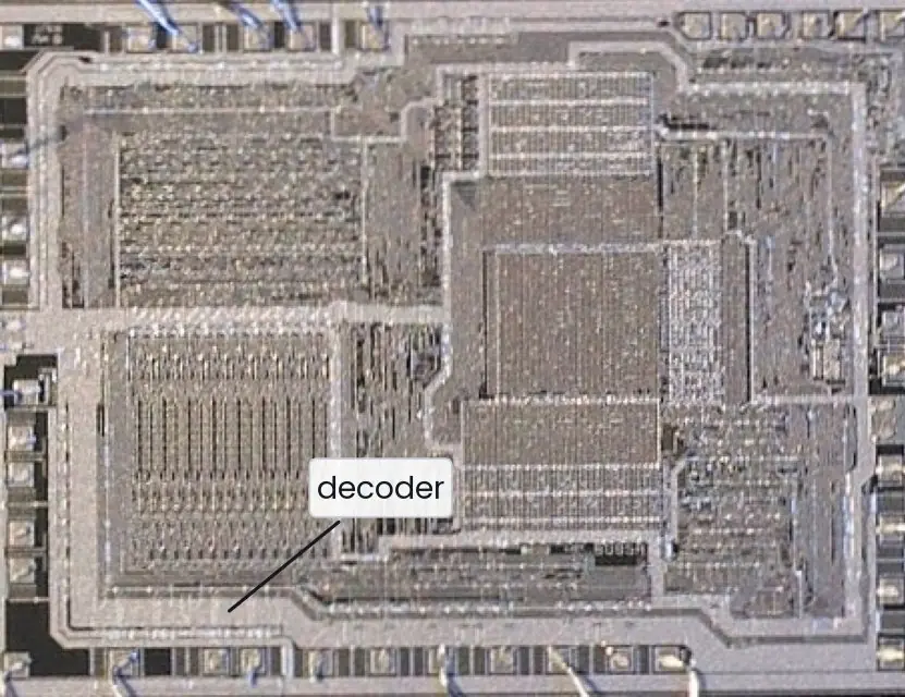


2.7.1 Eight advantages and uses of assembly language programming
- Speed. Assembly code becomes exactly the bytes you wrote, with no extra instructions added by a compiler. A delay or a data-copy loop therefore takes a known number of T-states (Fig. 2.3). This is why time-critical code is still written in assembly.
- Small memory use. Programs for the 8085 must fit in a few kilobytes of ROM. A hand-written routine often needs fewer bytes than the same task in a high-level language. Small chips in a washing machine or a smart meter therefore stay cheap.
- Direct control of hardware. Instructions such as IN, OUT and the interrupt controls talk to ports and chips directly. A BCA student can switch an LED on port 01H and see the result at once. This builds a clear picture of how software drives real devices.
- Understanding the CPU. Writing assembly shows what registers, flags and addressing modes do (Fig. 2.1). After the flag-setting behaviour of ADD and CMP is understood (Fig. 2.2), the behaviour of C and Java arithmetic becomes easier to explain. It is the best way to learn how a processor really works.
- Predictable timing. Because each instruction has a fixed T-state count, an engineer can compute execution time on paper. Control programs for motors, traffic lights and meters depend on this. High-level code on a modern operating system cannot promise the same timing.
- Device drivers and boot code. The first instructions that run when a computer starts, such as the BIOS and boot loader, are assembly. Drivers that handle interrupts use it for the few lines that must be fast. Nepali firmware engineers who repair or write embedded software meet this code often.
- Debugging and reverse engineering. A programmer who reads assembly can find why a program crashes and can study a virus or a faulty driver. Debuggers show registers and the stack as in Fig. 2.4. Security work, including the cyber-security courses of this programme, depends on this skill.
- Examination and laboratory practice. TU laboratory sheets ask for programs such as addition, largest number and multiplication. Writing, hand-assembling and testing them on a trainer kit builds careful habits of tracing and checking. These are skills that carry over to every later programming course.

Formula and fact sheet
- Instruction length 1–3 bytes; 16-bit values stored low byte first.
- Delay (one loop) = 14n + 4 T-states (MVI B,n / DCR B / JNZ); n = (T − 4) / 14.
- 16-bit counter loop = 24 T per pass; at 3 MHz 3000 T = 1 ms.
- CMP/CPI: Z = 1 if equal, CY = 1 if A < operand, A unchanged.
- INR/DCR leave CY alone; INX/DCX/DAD/LXI/MOV/MVI/LDA/STA do not set Z/S/P.
- To turn CY into a byte:
MVI A,00H ; ADC A. To test a byte for zero:ORA A. - Stack grows downward; CALL pushes the return address; PUSH/POP must pair up in reverse order.
- 8255 control words: 80H (all out), 90H (A in), 9BH (all in).
Chapter summary
- Instructions are 1–3 bytes; five addressing modes: immediate, register, direct, register-indirect, implied.
- Instruction groups: data transfer, arithmetic, logical/compare/rotate, branching, stack/I/O/machine control.
- Typical programs follow initialise → loop (process, advance pointer, count) → store → HLT; M with HL walks arrays.
- Delay loops use known T-states; one loop gives 14n + 4 T.
- The stack is LIFO in RAM; CALL/RET use it for return addresses.
- I/O may be memory-mapped or I/O-mapped; decoders create chip selects; the 8255 gives three programmable parallel ports.
Practice
- List the addressing modes of the 8085 with an example of each.
- State the difference between
RLCandRAL, and betweenCMP BandSUB B. - Write a program to find the smallest of 10 numbers stored from 2051H.
- Write a program to multiply 8-bit numbers 2050H × 2051H using repeated addition and state the 16-bit result storage.
- Write a program to add two BCD numbers and explain DAA.
- Compute the delay of:
MVI C,64H / LOOP: DCR C / JNZ LOOPat 2 MHz. - What value must be loaded in B to obtain a 5 ms delay on a 3 MHz 8085 using the one-loop routine? Is it possible? If not, what do you do?
- Write a program to count the number of negative numbers in a block of N bytes.
- Explain the operation of
CALLandRETwith the stack contents forCALL 2100Hat address 2005H, SP = 27FFH. - Differentiate between memory-mapped and I/O-mapped I/O. Write the 8255 control word and program to make port A input, port B output and port C output.
Answers and worked solutions
1. Immediate MVI A,05H; register MOV A,B; direct LDA 2050H; register indirect MOV A,M / LDAX B; implied CMA.
2. RLC rotates the 8 bits of A left, bit 7 goes to bit 0 and CY; RAL rotates through CY (a 9-bit rotate: CY enters bit 0, bit 7 goes to CY). SUB B stores A − B in A; CMP B sets the same flags but leaves A unchanged.
3. Same as Program 6 with N = 0AH and JC SKIP instead of JNC SKIP (smallest is retained in A); store at 2060H.
4. Program 4: result low byte 2052H, high byte 2053H (maximum FFH × FFH = FE01H).
5. Program 11. DAA corrects a binary sum of two BCD digits: it adds 6 to a nibble that exceeds 9 or has produced a carry.
6. n = 64H = 100, so T = 14 × 100 + 4 = 1404 T (the formula already includes the 7 T of MVI). At 2 MHz one T-state is 0.5 µs ⇒ 702 µs.
7. 5 ms = 15,000 T at 3 MHz ⇒ n = (15,000 − 4)/14 = 1071 > 255, so not possible with one 8-bit counter. Use a nested loop: 14BC + 18B + 4 = 15,000 with B = 5 gives C ≈ 213 (D5H), i.e. 15,004 T ≈ 5.001 ms; or a 16-bit counter loop with n = 15,000/24 = 625 = 0271H.
8. Like Program 13, but test bit 7: MOV A,M ; RLC ; JNC SKIP ; INR B (a negative number has S = 1 / bit 7 set → CY after RLC).
9. At 2005H the CALL (3 bytes) is followed by the instruction at 2008H. CALL pushes 2008H: SP 27FFH → 27FDH; memory 27FEH = 20H (high), 27FDH = 08H (low); PC ← 2100H. RET pops 27FDH/27FEH into PC (= 2008H) and SP returns to 27FFH.
10. Memory-mapped I/O uses memory instructions and the 16-bit address space; I/O-mapped uses IN/OUT with 8-bit port addresses. Control word: D7 = 1, mode 0, A input (D4 = 1), C upper output (D3 = 0), B output (D1 = 0), C lower output (D0 = 0) ⇒ 1001 0000 = 90H. Program: MVI A,90H ; OUT 83H ; IN 80H ; OUT 81H ; HLT copies port A to port B.
Model answers for Unit 2
Q1. Explain the addressing modes of the 8085 with one example of each. (5 marks)
An addressing mode is the way an instruction tells the CPU where its operand is (Fig. 2.1). The 8085 has five modes.
- Immediate. The data is part of the instruction.
MVI A,05H(bytes 3E 05) loads 05H into A, andLXI H,2050Hloads a 16-bit value. It is quick to write but the constant is fixed in the program. - Register. The operand is in a CPU register.
MOV B,A(47H) copies A into B. It is a one-byte instruction and the fastest, because no memory access is needed. - Direct. The instruction carries the 16-bit memory address.
LDA 2050H(3A 50 20) loads A from location 2050H, andSTA 2052Hstores A there. It takes three bytes and 13 T-states. - Register indirect. A register pair holds the address. After
LXI H,2050H, the instructionMOV A,M(7E) loads A from the address in HL.LDAX BandLDAX Dwork the same way. This mode walks through an array by incrementing HL. - Implied. The operand is fixed by the opcode itself.
CMA(2F) complements the accumulator,RALrotates it andSTCsets the carry flag.
Choosing the mode decides the instruction length (1, 2 or 3 bytes) and the time taken, so the register and indirect modes are preferred inside loops.
Q2. Write a one-loop delay routine for 1 ms on a 3 MHz 8085 and show the calculation. (5 marks)
A loop that does no useful work wastes a known number of T-states, so it makes a precise delay (Fig. 2.3).
        MVI B,D6H       ; 7 T
LOOP:   DCR B           ; 4 T
        JNZ LOOP        ; 10 T taken, 7 T on the last pass
Formula. The first pass costs 7 T for MVI. Each pass of DCR B plus JNZ costs 4 + 10 = 14 T, but the last pass costs 4 + 7 = 11 T. For n passes:
T = 7 + 14 (n - 1) + 11 = 14n + 4 T-states.
Calculation. At 3 MHz one T-state is 1 / 3,000,000 s = 0.333 microsecond, so 1 ms = 3000 T-states. Then 14n + 4 = 3000, so n = 2996 / 14 = 214, which is D6H.
Check 14 x 214 + 4 = 3000 T = 1.000 ms exactly. The simulator counted 3000 T for this routine (not counting HLT).
Limit. The largest count FFH gives 14 x 255 + 4 = 3574 T = 1.19 ms. For longer waits, nest two loops: T = 14BC + 18B + 4. With B = C = FFH this is 914,944 T = about 0.305 s, enough to make an LED blink visibly.
Q3. Describe the instruction groups of the 8085 with examples, and write a program to find the largest number in an array. (10 marks)
Introduction. The 8085 has 74 instructions (246 opcodes). They are one, two or three bytes long and fall into five functional groups (Section 2.2). The groups and their effect on the flags are summarised below.
| Group | Examples | Flags |
|---|---|---|
| Data transfer | MOV A,B, MVI C,05H, LDA 2050H, STA, LXI H,addr, XCHG |
none affected |
| Arithmetic | ADD B, ADI 05H, SUB, INR, DCR, DAD D, DAA |
all five (INR, DCR leave CY alone; DAD changes only CY) |
| Logical and compare | ANA, ORA, XRA, CMP, CPI, RLC, RAL, CMA |
per result (CMA none) |
| Branching | JMP, JZ, JNC, JM, CALL, RET, PCHL |
none affected (they test flags) |
| Stack, I/O and control | PUSH, POP, IN, OUT, EI, DI, RIM, SIM, HLT, NOP |
POP PSW restores flags |
- Data transfer copies bytes between registers, memory and I/O without changing the source or the flags.
- Arithmetic adds, subtracts, increments and decrements; DAA corrects a BCD sum.
- Logical instructions work bit by bit; CMP subtracts without storing, so only the flags change (CY = 1 if A is smaller).
- Branching changes the program counter, either always (JMP) or if a flag condition holds (JZ, JNC).
- Stack, I/O and control handle the stack, ports and interrupts.
Program: largest number in an array of 5 bytes at 2050H (result at 2060H). Real assembled listing and run:
2000  21 50 20  LXI H,2050H   ; HL points to the array
2003  0E 05     MVI C,05H     ; count = 5
2005  7E        MOV A,M       ; A = first element
2006  0D        DCR C         ; 4 elements remain
2007  23        NEXT: INX H   ; next element
2008  BE        CMP M         ; A - M, CY = 1 if M is bigger
2009  D2 0D 20  JNC SKIP      ; A bigger: keep it
200C  7E        MOV A,M       ; else A = M
200D  0D        SKIP: DCR C
200E  C2 07 20  JNZ NEXT
2011  32 60 20  STA 2060H
2014  76        HLT
With the data 34H, 9AH, 12H, F0H, 77H the program stores F0H at 2060H and takes 199 T-states (Fig. 2.2). The loop runs four times because the first element is already in A.
Conclusion. The five groups cover everything the CPU can do: move, calculate, decide, call and communicate. A good program mixes them, as the array program above does: transfer (MOV), compare (CMP), branch (JNC, JNZ) and store (STA).
Q4. Explain the stack of the 8085 and the working of PUSH, POP, CALL and RET with a diagram. (5 marks)
The stack is a last-in, first-out area of RAM addressed by the 16-bit stack pointer SP. It grows downward, and SP must be set first with LXI SP,27FFH (Fig. 2.4).
- PUSH rp decrements SP, stores the high byte, decrements SP again and stores the low byte. With SP = 27FFH,
PUSH Bstores B = 12H at 27FEH and C = 34H at 27FDH, so SP = 27FDH. - POP rp loads the low byte, then the high byte, and increments SP twice.
- CALL addr pushes the address of the next instruction on the stack and jumps. A CALL at 2005H pushes 2008H (20H at 27FEH, 08H at 27FDH).
- RET pops two bytes into the PC, so execution continues at 2008H.
Simulator results: after PUSH B, PUSH D, POP B, POP D the pairs are exchanged (BC = 5678H, DE = 1234H) and SP returns to 27FFH. A subroutine DOUBLE: ADD A ; RET called with A = 05H leaves 0AH.
Pushes and pops must match in reverse order, or RET will jump to a wrong address. Subroutines also use the stack to save registers they change.
Q5. Write an 8085 program to multiply two 8-bit numbers by repeated addition. Show a test run and the timing. (10 marks)
Introduction. The 8085 has no multiply instruction. Multiplication is done by adding the multiplicand to itself as many times as the multiplier says: 5 x 3 = 5 + 5 + 5.
The result of two 8-bit numbers can need 16 bits (FFH x FFH = FE01H), so the sum is kept in the register pair HL.
Algorithm.
- Load the multiplicand into DE (D = 00H, E = the number).
- Load the multiplier into C and clear HL.
- If C is zero, store 0000H and stop.
- Repeat:
DAD Dadds DE to HL; decrement C until C = 0. - Store HL (low byte at 2052H, high byte at 2053H).
Program (data at 2050H and 2051H, result at 2052H-2053H); real listing:
2000  3A 50 20  LDA 2050H     ; multiplicand
2003  5F        MOV E,A
2004  16 00     MVI D,00H     ; DE = 00xxH
2006  3A 51 20  LDA 2051H     ; multiplier
2009  4F        MOV C,A
200A  21 00 00  LXI H,0000H   ; sum = 0
200D  79        MOV A,C
200E  B7        ORA A         ; sets Z if C = 0
200F  CA 17 20  JZ STORE
2012  19        LOOP: DAD D   ; HL = HL + DE
2013  0D        DCR C
2014  C2 12 20  JNZ LOOP
2017  22 52 20  STORE: SHLD 2052H
201A  76        HLT
Test runs (real simulator).
| Multiplicand | Multiplier | Result at 2053H:2052H | T-states |
|---|---|---|---|
| F5H (245) | 12H (18) | 113AH (4410) | 516 (172 microseconds) |
| 05H | 03H | 000FH (15) | 156 |
| 05H | 00H | 0000H | 90 (JZ skips the loop) |
Analysis. Each pass of DAD D (10 T), DCR C (4 T) and JNZ (10 T) costs 24 T, except the last, which costs 21 T. The running time therefore depends on the multiplier: 18 passes take about 430 T, which fits the 516 T measured with the set-up and store instructions.
The method is simple but slow for large multipliers; a shift-and-add program needs at most 8 passes whatever the data.
Conclusion. The program uses four of the five instruction groups: data transfer (LDA, MOV, LXI), arithmetic (DAD, DCR), logical (ORA to test zero) and branching (JZ, JNZ).
The zero test matters, since without it a multiplier of 0 would make DCR C wrap to FFH and loop 256 times.