Unit 5 · 30 min read
Central Processing Unit and Computer Arithmetic
What the syllabus asks for 9
- General register organisation
- Stack organisation
- Instruction formats
- Addressing modes
- Data transfer and manipulation
- Program control
- RISC and CISC
- Computer arithmetic
- Seeing the ideas: RISC and CISC chips, stack, addressing, Booth, floating point and division
The CPU is the part that runs programs.
This unit covers how a general CPU organises its registers and stack, how instructions are formatted and addressed, the families of instructions, program control and interrupts, the RISC/CISC debate, and the arithmetic the ALU performs — including Booth's multiplication, division and floating point.
- General register organisation and the control word; stack organisation.
- Instruction formats (zero-, one-, two-, three-address) and addressing modes.
- Data-transfer, arithmetic, logic and shift instructions; program control, status bits, subroutines, interrupts.
- RISC versus CISC.
- Computer arithmetic: signed addition and subtraction, overflow, Booth's algorithm, restoring division, IEEE 754 floating point.
5.1 General register organisation
A CPU with several registers avoids slow memory accesses. In the textbook design, seven registers R1–R7 feed two multiplexers (MUX A and MUX B) which select the two ALU operands; the ALU output goes back through a decoder to the destination register.
  R1 … R7 ──► MUX A ─┐
                     ├──► ALU ──► (result) ──► destination register (via decoder)
  R1 … R7 ──► MUX B ─┘            OPR selects the operation
A control word specifies one micro-operation by selecting the three register fields and the operation:
| Field | Bits | Chooses |
|---|---|---|
| SELA | 3 | source register for ALU input A (000 = external input) |
| SELB | 3 | source register for ALU input B |
| SELD | 3 | destination register to load (000 = none) |
| OPR | 5 | the ALU operation |
| OPR | Operation | Symbol |
|---|---|---|
| 00000 | transfer A | TSFA |
| 00001 | increment A | INCA |
| 00010 | A + B | ADD |
| 00101 | A − B | SUB |
| 00110 | decrement A | DECA |
| 01000 | A ∧ B | AND |
| 01010 | A ∨ B | OR |
| 01100 | A ⊕ B | XOR |
| 01110 | complement A | COMA |
| 10000 | shift right A | SHRA |
| 11000 | shift left A | SHLA |
SELA = 010 (R2), SELB = 011 (R3), SELD = 001 (R1), OPR = 00010 (ADD): the 14-bit control word is 010 011 001 00010. After one clock the sum sits in R1. A whole instruction is a sequence of such control words.
5.2 Stack organisation
A stack is a LIFO store. A register stack uses a bank of registers with a stack pointer SP; a memory stack uses a region of RAM with SP in a CPU register (as on the 8085). Push and pop (memory stack growing toward lower addresses):
PUSH:  SP ← SP − 1 ;  M[SP] ← DR
POP :  DR ← M[SP] ;  SP ← SP + 1
A register stack adds FULL and EMPTY flags (stack-overflow and underflow checks) and works on SP ← SP ± 1 with a 6-bit pointer for 64 words. Stacks matter for subroutine calls, interrupts (saving PC), expression evaluation and recursion.
Reverse Polish notation
Stack machines evaluate postfix expressions with no brackets or precedence rules: A * B + C * D becomes A B * C D * +. Evaluate left to right: push operands; on an operator, pop two, apply, push the result.
Postfix: 3 4 + 6 2 − ×. Push 3, push 4; + → pop 4, 3 → push 7. Push 6, push 2; − → pop 2, 6 → push 4. × → pop 4, 7 → push 28. A stack-organised CPU gets zero-address instructions: PUSH 3, PUSH 4, ADD, PUSH 6, PUSH 2, SUB, MUL.
5.3 Instruction formats
An instruction has an opcode field, one or more operand/address fields and a mode field. The number of addresses determines the style:
| Format | Example: X = (A + B) × (C + D) | Notes |
|---|---|---|
| Three-address | ADD R1,A,B · ADD R2,C,D · MUL X,R1,R2 |
shortest programs, long instructions |
| Two-address | MOV R1,A · ADD R1,B · MOV R2,C · ADD R2,D · MUL R1,R2 · MOV X,R1 |
most common (x86-style); destination also a source |
| One-address | LOAD A · ADD B · STORE T · LOAD C · ADD D · MUL T · STORE X |
accumulator machines (8085, basic computer) |
| Zero-address | PUSH A, PUSH B, ADD, PUSH C, PUSH D, ADD, MUL, POP X |
stack machines |
More address fields ⇒ fewer instructions but more bits per instruction and more memory accesses per instruction.
5.4 Addressing modes
An addressing mode is the rule for finding an operand's effective address (EA) from the instruction's address field. Why modes exist: to give programmers pointers, loops over arrays, relocatable code and shorter instructions.
| Mode | Operand location / EA | Typical use |
|---|---|---|
| Implied | named by the opcode (accumulator, stack top) | CMA, zero-address stack ops |
| Immediate | the operand is in the instruction | constants (MVI A,05H) |
| Register | operand in a register | speed |
| Register indirect | EA = register contents | pointers (MOV A,M) |
| Autoincrement / autodecrement | register indirect, then register ± 1 | stepping through arrays, stack |
| Direct (absolute) | EA = address field | global variables |
| Indirect | EA = M[address field] | pointers in memory |
| Relative | EA = PC + address field | branches, position-independent code |
| Indexed | EA = index register + address field | array elements |
| Base register | EA = base register + address field | relocation of programs, segments |
Instruction at address 200, address field = 500, with PC = 201 (already incremented), index register XR = 100, R1 = 400, M[500] = 800, M[400] = 700, M[800] = 300.
| Mode | EA | Operand |
|---|---|---|
| Direct | 500 | M[500] = 800 |
| Immediate | — | 500 |
| Indirect | M[500] = 800 | M[800] = 300 |
| Relative | 201 + 500 = 701 | M[701] |
| Indexed | 500 + 100 = 600 | M[600] |
| Register | — | R1 = 400 |
| Register indirect | R1 = 400 | M[400] = 700 |
| Autoincrement | R1 = 400 (then R1 ← 401) | M[400] = 700 |
5.5 Data transfer and manipulation
Data-transfer instructions
Move data without changing it: LOAD (memory → register), STORE (register → memory), MOVE (register → register), EXCHANGE, PUSH, POP, INPUT, OUTPUT.
Arithmetic instructions
INC, DEC, ADD, SUB, MUL, DIV, ADDC (add with carry), SUBB (subtract with borrow), NEG (two's complement).
Logical and bit-manipulation instructions
CLR, COM, AND, OR, XOR, CLRC, SETC, COMC (carry), and bit tricks built from them:
- Clear selected bits: AND with a mask that has 0 in those positions (
1011 0110 AND 1111 0000 = 1011 0000). - Set selected bits: OR with a mask having 1s there.
- Complement selected bits: XOR with 1s there.
Shift instructions
| Shift | Meaning | Fill |
|---|---|---|
| Logical right/left | slide all bits | 0 enters |
| Arithmetic right | divides a signed number by 2 | sign bit is replicated |
| Arithmetic left | multiplies by 2 | 0 enters; overflow if the sign changes |
| Rotate | circular | the bit that leaves re-enters |
| Rotate through carry | circular with carry as the 9th bit | CY enters |
Example: arithmetic right shift of 1110 0100 (−28) gives 1111 0010 (−14); a logical right shift would give 0111 0010 (+114).
5.6 Program control
Program-control instructions change the PC: BR (branch), JMP, conditional branches (BZ, BNZ, BC, BNC, BP, BM, BV), CALL, RET, compare and test (CMP, TST).
Status bit conditions
The status register (flags) records ALU outcomes: C carry, S sign, Z zero, V overflow. Conditional branches test them. After comparing A and B (A − B):
| Condition | Test |
|---|---|
| A = B | Z = 1 |
| A ≠ B | Z = 0 |
| A > B (unsigned) | C = 0 and Z = 0 |
| A < B (unsigned) | C = 1 |
| A < B (signed) | S ⊕ V = 1 |
| A ≥ B (signed) | S ⊕ V = 0 |
Subroutine call and return
CALL pushes the return address and loads the PC with the subroutine's address; RET pops it. The stack allows nested and recursive calls, unlike the basic computer's BSA (Unit 3).
Program interrupt
An interrupt is a transfer of control forced by an event, not by the program. The CPU completes the current instruction, saves the PC and status on the stack, loads the service-routine address, and RETurns (IRET) afterwards.
| Type | Source | Examples |
|---|---|---|
| External interrupt | outside hardware | I/O device ready, timer, power failure, operator key |
| Internal (trap) | inside the CPU, caused by the running program | divide by zero, overflow, illegal opcode, protection violation, page fault |
| Software interrupt | a deliberate instruction | system calls (INT, SVC, RST n) |
Interrupts can be vectored (the device supplies the address) or non-vectored (fixed address), and prioritised (Unit 6).
5.7 RISC and CISC
| CISC (complex instruction set) | RISC (reduced instruction set) | |
|---|---|---|
| Instructions | many (100–300+), powerful, variable length | few (≈ 50–100), simple, fixed length |
| Cycles per instruction | many, varying | mostly 1 cycle |
| Memory access | many instruction types access memory | only LOAD and STORE access memory (load/store architecture) |
| Addressing modes | many | few |
| Registers | few | large register file |
| Control unit | microprogrammed | hardwired |
| Pipelining | harder | easy and efficient |
| Compiler | simple (instructions close to HLL) | does more work |
| Code size | small | larger |
| Examples | VAX, Intel x86, Motorola 68000 | ARM, MIPS, RISC-V, SPARC, PowerPC |
Neither is simply "better": modern x86 chips translate CISC instructions into RISC-like micro-ops internally, and ARM dominates phones for power efficiency.
5.8 Computer arithmetic
Signed integers and addition/subtraction
- Sign-magnitude: sign bit + magnitude; two zeros; awkward addition.
- 1's complement: invert bits; two zeros.
- 2's complement (used everywhere): −x = x′ + 1; single zero; range of n bits −2ⁿ⁻¹ … 2ⁿ⁻¹ − 1 (8 bits: −128 … 127). Add and subtract use the same adder: A − B = A + (B′ + 1).
Overflow (result outside the range) happens only when two numbers of the same sign give a result of the opposite sign. Detect it as V = carry into the sign bit XOR carry out of the sign bit.
Example (8 bits) 0111 1111 + 0000 0001 = 1000 0000 (127 + 1 = −128): carry into MSB = 1, carry out = 0 ⇒ V = 1, overflow.
Multiplication — shift-and-add
Multiply by adding the multiplicand once per 1-bit of the multiplier, shifted. Hardware keeps A (accumulator, initially 0), Q (multiplier), M (multiplicand) and a counter.
For each bit of Q: if Q₀ = 1, A ← A + M; then shift A, Q right together. After n steps AQ holds the 2n-bit product (for unsigned numbers).
Booth's algorithm (signed, two's complement)
Booth's method handles negative numbers without special cases and skips runs of 1s. It keeps an extra bit Q₋₁ (initially 0) and looks at the pair (Q₀, Q₋₁) at each step:
| Q₀ Q₋₁ | Action before the shift |
|---|---|
| 00 or 11 | none |
| 10 (start of a run of 1s) | A ← A − M |
| 01 (end of a run of 1s) | A ← A + M |
Then arithmetic shift right the combined A, Q, Q₋₁ (the sign bit of A is kept). Repeat for n bits; the product is in AQ.
M = −9 = 10111, Q = −13 = 10011, A = 00000, Q₋₁ = 0. (The values were generated and checked by the verifier script.)
| Step | Q₀Q₋₁ | Operation | A | Q | Q₋₁ |
|---|---|---|---|---|---|
| start | 00000 | 10011 | 0 | ||
| 1 | 10 | A ← A − M = 01001, shift | 00100 | 11001 | 1 |
| 2 | 11 | shift | 00010 | 01100 | 1 |
| 3 | 01 | A ← A + M = 11001, shift | 11100 | 10110 | 0 |
| 4 | 00 | shift | 11110 | 01011 | 0 |
| 5 | 10 | A ← A − M = 00111, shift | 00011 | 10101 | 1 |
Product = AQ = 00011 10101 = 0001110101₂ = 117. ✔ ((−9) × (−13) = 117.)
M = 0111, Q = 0011, A = 0000, Q₋₁ = 0.
| Step | Q₀Q₋₁ | Operation | A | Q | Q₋₁ |
|---|---|---|---|---|---|
| 1 | 10 | A ← A − M = 1001, shift | 1100 | 1001 | 1 |
| 2 | 11 | shift | 1110 | 0100 | 1 |
| 3 | 01 | A ← A + M = 0101, shift | 0010 | 1010 | 0 |
| 4 | 00 | shift | 0001 | 0101 | 0 |
Product = 0001 0101₂ = 21 ✔ (verified by the script).
Division
Restoring division (unsigned): A = 0, Q = dividend, M = divisor. Repeat n times: shift A,Q left one bit; A ← A − M; if A < 0, restore (A ← A + M) and set Q₀ = 0, else set Q₀ = 1. At the end Q is the quotient and A the remainder.
Non-restoring division avoids the restore step by adding M in the next cycle when A went negative.
A = 0000, Q = 1101, M = 0011.
| Step | After shift | A − M | Action | A | Q |
|---|---|---|---|---|---|
| 1 | A = 0001 | negative | restore, q = 0 | 0001 | 1010 |
| 2 | A = 0011 | 0000 | q = 1 | 0000 | 0101 |
| 3 | A = 0000 | negative | restore, q = 0 | 0000 | 1010 |
| 4 | A = 0001 | negative | restore, q = 0 | 0001 | 0100 |
Quotient Q = 0100 = 4, remainder A = 0001 = 1 ✔ (3 × 4 + 1 = 13).
Floating-point numbers (IEEE 754)
A floating-point number is ±1.f × 2ᵉ. Single precision (32 bit): 1 sign bit, 8-bit biased exponent (bias 127), 23-bit fraction (the leading 1 is implicit). Double precision (64 bit): 1 + 11 (bias 1023) + 52.
12.375 = 1100.011₂ = 1.100011 × 2³. Sign 0; exponent 3 + 127 = 130 = 10000010; fraction 10001100000000000000000. Hex 41460000.
Check −5.75 = −101.11₂ = −1.0111 × 2² → sign 1, exponent 129 = 10000001, fraction 0111… ⇒ C0B80000. Decoding 3F400000: sign 0, exponent 01111110 = 126 → 2⁻¹, fraction .1 ⇒ 1.1₂ × 2⁻¹ = 1.5 × 0.5 = 0.75. (All verified by script.)
Floating-point addition/subtraction needs four steps: (1) align the exponents by shifting the smaller number's mantissa right; (2) add or subtract the mantissas; (3) normalise the result (shift so it is 1.f again, adjusting the exponent); (4) round and check for overflow/underflow.
Example 0.5 + 0.375: 0.5 = 1.0 × 2⁻¹, 0.375 = 1.1 × 2⁻²; align: 0.11 × 2⁻¹; add: 1.0 + 0.11 = 1.11 × 2⁻¹ = 0.875.
Multiplication: multiply mantissas, add exponents (subtract one bias), normalise; division: divide mantissas, subtract exponents.
5.9 Seeing the ideas: RISC and CISC chips, stack, addressing, Booth, floating point and division
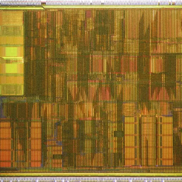
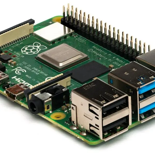
This unit mixes organisation and arithmetic, so the visuals do both jobs. The plate sets a real CISC chip beside a real RISC board.
The figures then show a stack evaluating an expression, the effective address under each addressing mode with numbers, Booth's algorithm step by step, the exact IEEE 754 bits of a number, and restoring division.
Every number was recomputed with Python (Booth and division traces, struct for the 32-bit floating-point words).


5.9.1 Eight features of a RISC processor
- Small, simple instruction set. A RISC chip has perhaps 50 to 100 instructions, each doing one small job. Simple instructions are easy to decode and to test. Compilers combine them to do bigger work.
- Fixed instruction length. Every ARM instruction is 4 bytes (Plate 5.1c), so the next instruction always starts at a known place. The decoder is simple and the pipeline never waits to find where an instruction ends. A CISC chip such as the x86 must decode 1 to 15 bytes.
- Load/store architecture. Only LOAD and STORE touch memory; arithmetic works on registers. This keeps most instructions short and fast because memory is slow. Programs first load data into registers, compute, and then store the result.
- Large register file. RISC chips have 32 or more general registers, so most values stay inside the CPU. Fewer memory accesses make programs faster and save energy. This is one reason phones with ARM chips last long on a battery.
- One instruction per cycle. Most instructions finish in one clock cycle once the pipeline is full (Unit 8). The designer can then predict performance. Fast simple steps beat slow complex ones when many are overlapped.
- Hardwired control. Because the instructions are simple, a RISC control unit uses gates, not a microprogram (Unit 4). There is no control-memory read on each step, so the clock can run faster. The chip is also smaller.
- Few addressing modes. RISC uses register, immediate and base-plus-offset addressing only. Fewer modes mean a simpler effective-address calculation (Fig. 5.2) and a shorter pipeline stage. Complex addressing is built from several simple instructions.
- Pipeline-friendly design. Equal-length, equal-time instructions fit neatly into pipeline stages with few stalls. This is why ARM, MIPS and RISC-V designs reach high speed with modest hardware. It also explains why ARM dominates phones, from budget handsets sold in Nepal to flagship models.
Formula and fact sheet
- 2's complement: −x = x′ + 1; n-bit range −2ⁿ⁻¹ … 2ⁿ⁻¹ − 1; overflow V = C_in(MSB) ⊕ C_out(MSB).
- Booth: look at Q₀Q₋₁: 10 → A − M, 01 → A + M, 00/11 → shift only; arithmetic right shift; n steps.
- Restoring division: shift left, A − M, restore if negative, Q₀ = 1/0.
- IEEE single: value = (−1)ˢ × 1.f × 2^{e-127}; double bias 1023.
- EA: indexed = base + index; relative = PC + offset; indirect = M[address].
- Instructions needed for X = (A+B)(C+D): 3-address 3, 2-address 6, 1-address 7, 0-address 8.
Chapter summary
- A register-organised CPU selects ALU operands with two multiplexers and a control word SELA/SELB/SELD/OPR.
- A stack gives LIFO storage, supports calls and interrupts, and evaluates postfix expressions.
- Instruction formats range from three-address to zero-address; addressing modes locate operands flexibly.
- Program control uses flags C, S, Z, V; subroutine calls and interrupts save the return state on the stack.
- RISC: simple, fixed-length, load/store, hardwired, pipeline-friendly; CISC: complex, microprogrammed.
- The ALU adds/subtracts with 2's complement, multiplies with shift-and-add or Booth, divides by restoring/non-restoring, and handles reals as IEEE 754 floating point.
Practice
- Write the control word for R4 ← R5 − R6 in the seven-register CPU.
- Convert A × B + C × D − E to postfix and evaluate it for A = 2, B = 3, C = 4, D = 5, E = 6.
- Write programs for X = (A + B) × (C − D) in three-, two-, one- and zero-address styles.
- Explain any six addressing modes with the effective address calculation.
- Differentiate between RISC and CISC.
- Perform (−6) × 5 with 5-bit Booth's algorithm.
- Divide 13 by 3 by the restoring method (4 bits).
- Represent −5.75 in IEEE 754 single precision.
- Add 0110 0111 and 0101 1001 (8-bit two's complement) and detect overflow.
- Distinguish external, internal and software interrupts with examples.
Answers and worked solutions
1. SELA = 101 (R5), SELB = 110 (R6), SELD = 100 (R4), OPR = 00101 (SUB): 101 110 100 00101.
2. A B * C D * + E −. 2·3 = 6; 4·5 = 20; 6 + 20 = 26; 26 − 6 = 20.
3. 3-address: SUB R1,C,D · ADD R2,A,B · MUL X,R2,R1. 2-address: MOV R1,A · ADD R1,B · MOV R2,C · SUB R2,D · MUL R1,R2 · MOV X,R1. 1-address: LOAD C · SUB D · STORE T · LOAD A · ADD B · MUL T · STORE X. 0-address: PUSH A · PUSH B · ADD · PUSH C · PUSH D · SUB · MUL · POP X.
4. See the table in 5.4: e.g. indexed EA = XR + address field; relative EA = PC + offset; indirect EA = M[address]; register indirect EA = R.
5. See 5.7: RISC = few fixed-length, load/store, hardwired, big register file; CISC = many variable-length, microprogrammed.
6. M = −6 = 11010, Q = 5 = 00101. Following the Booth steps (Q₀Q₋₁ = 10 → A − M; 01 → A + M) gives AQ = 1111100010₂ = −30 (checked by the verifier).
7. The table in 5.8 gives quotient 4, remainder 1.
8. −5.75 = −1.0111 × 2² → C0B80000 (1 10000001 01110000000000000000000).
9. 0110 0111 (103) + 0101 1001 (89) = 1100 0000 (−64 as signed). Carry into MSB = 1, carry out = 0 ⇒ V = 1, overflow (the true sum 192 > 127).
10. External: I/O device ready, timer. Internal (trap): divide by zero, overflow, illegal opcode, page fault. Software: system call INT n, RST n.
Model answers for Unit 5
Q1. Differentiate between RISC and CISC architectures. (5 marks)
CISC (complex instruction set computer) has many powerful instructions of varying length, many addressing modes and a microprogrammed control unit; the Intel x86 is the usual example.
RISC (reduced instruction set computer) has a small set of simple, fixed-length instructions, a load/store architecture and a hardwired control unit; ARM, MIPS and RISC-V are examples (Plate 5.1).
| Point | CISC | RISC |
|---|---|---|
| Instructions | 100-300 or more, complex | 50-100, simple |
| Length | variable (x86: 1-15 bytes) | fixed (ARM: 4 bytes) |
| Cycles per instruction | many, varying | mostly 1 |
| Memory access | many instructions | only LOAD and STORE |
| Addressing modes | many | few |
| Registers | few | large register file (32 or more) |
| Control unit | microprogrammed | hardwired |
| Pipelining | harder | easy and efficient |
| Code size | smaller | larger |
| Compiler | simple | does more work |
Neither is simply better. Modern x86 chips translate CISC instructions into RISC-like micro-operations inside, and ARM leads in phones because of low power.
Q2. Explain the addressing modes with the effective address of each, using one set of numbers. (5 marks)
An addressing mode tells the CPU how to find the operand. The effective address (EA) is the final memory address of the operand. Take A = 500, R1 = 400, XR = 100, PC = 201 and M[500] = 800 (Fig. 5.2).
- Immediate. The operand is the address field itself: operand = 500. No memory access for the operand, so it is fastest, but the value is fixed.
- Direct. EA = A = 500. One memory access.
- Indirect. EA = M[A] = M[500] = 800. Two memory accesses; useful for pointers.
- Register indirect. EA = content of R1 = 400. One access, and the register can step through an array.
- Indexed. EA = A + XR = 500 + 100 = 600. Changing XR walks through a table starting at A.
- Relative. EA = A + PC = 500 + 201 = 701. The address depends on the position of the instruction, so the program can be moved in memory (relocatable code); branches use it.
Other modes are register (the operand is in a register) and base-register (EA = base + A), which relocates a whole program by changing one register. The choice of mode trades instruction length and speed against flexibility.
Q3. Explain Booth's multiplication algorithm with a flowchart description and a worked example. (10 marks)
Introduction. Booth's algorithm multiplies two signed numbers in two's complement form.
It treats a run of 1s in the multiplier as a single subtraction at the start of the run and an addition after its end, so long runs of 1s need few operations and negative multipliers need no special case.
Registers. M holds the multiplicand, Q the multiplier, AC (the accumulator) starts at 0, Q-1 is an extra bit starting at 0, and a counter SC holds the number of bits n.
Algorithm.
- Set AC = 0, Q-1 = 0, SC = n.
- Look at the pair (Q0, Q-1), the last bit of Q and the extra bit.
- If the pair is 10, do AC <- AC - M. If it is 01, do AC <- AC + M. If it is 00 or 11, do nothing.
- Perform an arithmetic shift right of AC, Q and Q-1, keeping the sign bit of AC.
- Decrement SC; if SC is not 0, go to step 2.
- The product is in AC:Q.
Worked example: 7 x (-3), n = 4 (real trace, Fig. 5.3). M = 0111, Q = 1101.
| Step | Q0 Q-1 | Action | AC | Q | Q-1 |
|---|---|---|---|---|---|
| 1 | 1 0 | AC - M | 1100 | 1110 | 1 |
| 2 | 0 1 | AC + M | 0001 | 1111 | 0 |
| 3 | 1 0 | AC - M | 1101 | 0111 | 1 |
| 4 | 1 1 | shift only | 1110 | 1011 | 1 |
The product AC:Q = 1110 1011 is -21 in 8-bit two's complement, and 7 x (-3) = -21. A second check, (-3) x 5 with M = 1101 and Q = 0101, gives 1111 0001 = -15.
Advantages and limits.
- It handles signed numbers directly, with no correction step.
- It is fast for multipliers with long runs of 1s, for example 0111 1110 needs one subtraction and one addition.
- Its worst case is an alternating pattern such as 0101, which needs an add or subtract at every step.
- It needs an adder and a shifter only; no separate sign logic is required.
Conclusion. Booth's algorithm gives correct signed products by examining two multiplier bits at a time, using add, subtract and shift. It is the basis of most hardware multipliers.
Q4. Represent 13.625 in IEEE 754 single precision. Explain the format. (5 marks)
IEEE 754 single precision uses 32 bits: 1 sign bit, 8 exponent bits (bias 127) and 23 fraction bits. A normalised number is (-1)^s x 1.f x 2^{e - 127} (Fig. 5.4).
- Convert to binary: 13 = 1101 and 0.625 = 0.101, so 13.625 = 1101.101.
- Normalise: 1101.101 = 1.101101 x 2^{3}.
- Sign = 0 (positive).
- Biased exponent = 3 + 127 = 130 = 10000010.
- Fraction = the bits after the leading 1: 10110100000000000000000 (23 bits).
The word is 0 10000010 10110100000000000000000 = 415A0000 in hexadecimal (verified with Python).
To decode, reverse the steps: C1D00000 has sign 1, exponent 10000011 = 131 so the power is 4, and fraction 101 so 1.101 x 2^{4} = 11010b = -26.0.
Numbers such as 0.1 cannot be written exactly in binary, so -0.1 becomes BDCCCCCD, an approximation; this is why floating-point comparisons for equality are risky. Two more points complete the format.
The bias of 127 lets the exponent be stored as an unsigned number, so that real exponents from -126 to +127 fit in the 8 bits and comparing two positive floats can be done like comparing integers.
The leading 1 of the normalised mantissa is not stored (the hidden bit), which gives 24 bits of precision from 23 stored bits, about 7 decimal digits.
The double-precision format uses 64 bits (1, 11 and 52, bias 1023) for about 16 digits.
Q5. Explain stack organisation and reverse Polish notation. Write programs for X = (A + B) x (C + D) on zero-, one-, two- and three-address machines. (10 marks)
Introduction. A stack is a last-in, first-out storage structure. Its address is held in a stack pointer SP; PUSH stores a value and POP removes the top value.
It can be a set of CPU registers (register stack) or a region of memory (memory stack, as in the 8085). A stack machine needs no operand addresses for arithmetic: operations act on the top elements.
Reverse Polish notation (RPN). Normal (infix) notation needs brackets and priorities. In postfix notation the operator follows its operands, so (A + B) x (C + D) becomes A B + C D + x.
It is evaluated left to right with a stack: a value is pushed, and an operator pops two values, applies itself and pushes the result (Fig. 5.1).
With A = 2, B = 3, C = 4, D = 5: push 2, push 3, + gives 5; push 4, push 5, + gives 9; x gives 45.
Instruction formats and programs for X = (A + B) x (C + D).
| Format | Program | Instructions |
|---|---|---|
| Three-address | ADD R1,A,B ; ADD R2,C,D ; MUL X,R1,R2 |
3 |
| Two-address | MOV R1,A ; ADD R1,B ; MOV R2,C ; ADD R2,D ; MUL R1,R2 ; MOV X,R1 |
6 |
| One-address | LOAD A ; ADD B ; STORE T ; LOAD C ; ADD D ; MUL T ; STORE X |
7 |
| Zero-address (stack) | PUSH A ; PUSH B ; ADD ; PUSH C ; PUSH D ; ADD ; MUL ; POP X |
8 |
Comparison. The three-address format needs the fewest instructions but each is long, because it holds three addresses.
The zero-address format needs the most instructions, but arithmetic instructions are very short and no registers have to be named. The one-address format is the accumulator style of the 8085 and the basic computer.
Advantages of stacks. They make evaluation of expressions simple, give subroutine call and return (the return address is pushed), and allow recursion and nested interrupts. The Java virtual machine and many calculators are stack machines.
Conclusion. A stack with RPN turns expression evaluation into a mechanical push-and-pop process, and the choice of instruction format trades program length against instruction length.
Q6. Divide 13 by 3 using the restoring division method and show each step. (5 marks)
In restoring division the dividend is held in Q, the remainder register A starts at 0, and the divisor is in B = 3.
Repeat n = 4 times: shift A:Q left one place; subtract B from A; if A is negative, set the new quotient bit to 0 and restore A by adding B back; otherwise set the bit to 1 (Fig. 5.5).
| Step | After shift A | A - 3 | Action | A | Quotient bit |
|---|---|---|---|---|---|
| 1 | 0001 | -2 | restore | 1 | 0 |
| 2 | 0011 | 0 | keep | 0 | 1 |
| 3 | 0000 | -3 | restore | 0 | 0 |
| 4 | 0001 | -2 | restore | 1 | 0 |
The quotient bits 0 1 0 0 give quotient = 4 and remainder = 1.
Check 3 x 4 + 1 = 13. The method is called restoring because a failed subtraction is undone by adding the divisor back. The non-restoring method avoids that extra addition by adding the divisor in the next step instead, which saves time.