Unit 6 · 29 min read
Input–Output Organisation
What the syllabus asks for 7
- The I/O interface
- Asynchronous data transfer
- Modes of transfer
- Priority interrupts
- Direct memory access
- I/O processors and communication processors
- Seeing the ideas: interface chips, handshaking, serial frames, priority chain, DMA and bit stuffing
A computer is useless if it cannot talk to the world. Devices are thousands of times slower than the CPU and speak different formats, so a computer needs interfaces and a strategy for transferring data.
This unit covers the I/O interface, the three transfer methods (programmed, interrupt-driven, DMA), interrupt priority, and I/O processors.
- The I/O bus and interface; memory-mapped versus isolated I/O.
- Asynchronous data transfer: strobe and handshaking.
- Programmed I/O, interrupt-initiated I/O, priority interrupts and the daisy chain.
- Direct memory access (DMA): controller, transfer modes, a worked timing example.
- I/O processors and serial communication protocols.
6.1 The I/O interface
An interface sits between the CPU buses and a peripheral.
Why it is needed: (1) peripherals are electromechanical with different signal levels and formats; (2) their data rate is much lower than the CPU's; (3) their data formats and word lengths differ; (4) the CPU must be able to select one among many devices.
        data bus    ┌────────────┐   data (device format)
 CPU ◄════════════► │  interface │ ◄════════════►  peripheral
 address bus ═════► │  (ports,   │ ◄── status / control ──►
 control bus (R/W)► │  registers)│
                    └────────────┘
An interface has registers: a data register (data in/out), a status register (ready/busy/error flags) and a control register (commands to the device), and a small decoder that recognises its own address.
I/O bus and addressing
Two ways to give devices addresses:
| Isolated (I/O-mapped) | Memory-mapped | |
|---|---|---|
| Address space | separate; special IN/OUT instructions | shares the memory address space |
| Control line | separate I/O read/write signals | the ordinary memory read/write |
| Instructions | few (IN, OUT) | any memory instruction works on device registers |
| Memory used | none lost | some addresses lost to devices |
| Example | 8085 IN/OUT, x86 ports |
ARM, MIPS, most microcontrollers |
6.2 Asynchronous data transfer
CPU and device have different clocks, so they must agree on when data is valid.
Strobe control — one control line from one side tells the other when the data is valid.
- Source-initiated strobe: the source places data on the bus, then pulses the strobe; the destination latches data on the strobe's edge. Weakness: the source cannot know whether the destination received it.
- Destination-initiated strobe: the destination pulses the strobe to request data; the source supplies it. Weakness: the destination cannot know the data is valid.
Handshaking fixes both weaknesses with two lines forming a request–acknowledge loop:
Source-initiated handshake:
  1. source puts data on the bus, then raises  DATA VALID
  2. destination accepts the data, raises       DATA ACCEPTED
  3. source drops DATA VALID, removes the data
  4. destination drops DATA ACCEPTED   → ready for the next transfer
Handshaking guarantees delivery whatever the relative speeds; it is used by parallel ports (Centronics) and the 8255's mode 1.
Asynchronous serial transmission sends characters one bit at a time with start bit (0), 5–8 data bits (LSB first), an optional parity bit, and 1–2 stop bits (1). The line idles at 1.
At 9600 baud with 8N1 (one start, 8 data, no parity, one stop = 10 bits per character) the rate is 960 characters per second.
6.3 Modes of transfer
1. Programmed I/O (polling)
The CPU runs an I/O program that repeatedly tests the device's status flag until it is ready, then moves one word.
loop:  IN   status_port      ; read the status
       ANI  01H              ; ready bit?
       JZ   loop             ; not ready: keep polling (busy wait)
       IN   data_port        ; ready: read the byte
Simple, but the CPU is tied up doing nothing useful while it waits. Fine for fast devices or trivial systems.
2. Interrupt-initiated I/O
The CPU does other work; when the device is ready it raises an interrupt. The CPU finishes the current instruction, saves the PC (and flags), jumps to the interrupt service routine (ISR) at the vector address, transfers the data, restores the state and resumes.
| Programmed (polling) | Interrupt-driven |
|---|---|
| CPU checks the device repeatedly | device signals the CPU |
| CPU is busy-waiting | CPU free for other work |
| simple hardware | needs interrupt hardware and ISRs |
| response time depends on the polling loop | fast, but each word costs interrupt overhead |
Vectored interrupts: the device supplies the vector address (or an interrupt-type number) directly; non-vectored: the CPU jumps to a fixed address and then finds out who interrupted by polling.
3. Direct memory access (DMA)
For fast, bulk transfers (disk, network) even interrupts per byte are too slow. DMA lets a DMA controller move blocks directly between a device and memory without the CPU touching each word (Section 6.5).
6.4 Priority interrupts
With several devices, the system must decide who is served first and what to do if another interrupt arrives mid-service.
Software polling
One common interrupt branches to a routine that polls each device's status in priority order. Simple, but the polling time makes the lowest-priority device slow.
Daisy-chain (hardware) priority
Devices are connected in a chain; the interrupt-acknowledge signal enters the highest-priority device. Each device has a PI (priority-in) and PO (priority-out) line:
 CPU INTA ──► [Device 1] PI → PO ──► [Device 2] PI → PO ──► [Device 3] …
              (highest)                                      (lowest)
 A device that is requesting keeps PO = 0 (blocks the chain) and puts its vector on the bus;
 a device that is not requesting passes PI → PO.
Cheap and scalable, but the priorities are fixed by position and one failed device can break the chain.
Parallel priority hardware
A priority encoder with an interrupt mask register: each device has a request line; a mask bit can disable it; the encoder outputs the vector of the highest-priority unmasked request. More flexible and faster than the daisy chain; masks allow selective disabling.
The 8085 and the 8259
The 8085 has built-in priority (TRAP > RST 7.5 > 6.5 > 5.5 > INTR). For more devices, a programmable 8259 interrupt controller accepts 8 request lines (cascadable to 64), prioritises them and supplies the vector to the CPU.
Enabling, masking and nesting
Maskable interrupts can be disabled (DI, mask register); non-maskable ones (TRAP, power-fail) cannot. A higher-priority interrupt may interrupt a lower-priority ISR (nesting) provided the ISR saves state on the stack and re-enables interrupts.
6.5 Direct memory access
Why DMA
Interrupt-driven transfer costs maybe 10–50 CPU cycles per word. A disk delivering 50 MB/s would swamp the CPU. With DMA the CPU sets up the transfer and is interrupted once per block.
The DMA controller
Registers inside the DMA controller (e.g. Intel 8257/8237): an address register (memory address of the next transfer), a word count register (words remaining), a control register (direction, mode) and a status register.
The DMA procedure
- The CPU programs the DMA controller: memory start address, word count, direction (read from or write to the device), and starts it.
- The device raises DREQ (DMA request) when it has data.
- The controller asserts HOLD (bus request) to the CPU.
- The CPU finishes its current bus cycle, releases the address, data and control buses (tri-states them), and replies HLDA (hold acknowledge).
- The controller puts the memory address on the address bus and asserts the read/write strobes; the data goes directly between device and memory (the controller sends DACK to the device).
- Address register ++, word count −−. Repeat steps 5–6 until the count is 0.
- The controller drops HOLD; the CPU regains the bus; the controller raises an interrupt to say "block done".
DMA transfer modes
| Mode | How it takes the bus | Effect |
|---|---|---|
| Burst (block) mode | keeps the bus for the whole block | fastest transfer; CPU stalled for the duration |
| Cycle stealing | takes the bus for one cycle per word, then returns it | CPU slowed slightly; smooth; the usual choice |
| Transparent mode | transfers only when the CPU is not using the bus | no CPU slowdown; slower transfer, complex hardware |
A device delivers 4 KB (4096 words) at 20 KB/s, so the block takes about 205 ms to arrive.
In interrupt mode each word costs about 20 µs of CPU time for the ISR (save, move, restore): 4096 × 20 µs = 82 ms of CPU time (40% of the 205 ms; at 1 MB/s the ISR could not keep up at all, since 20 µs per word allows only 50,000 words per second).
With DMA in cycle-stealing mode, the CPU spends perhaps 20 µs to program the controller and 20 µs for the completion interrupt, and loses at most one memory cycle (say 0.5 µs) per word: 4096 × 0.5 µs = 2 ms of bus time — a roughly 40× saving.
Memory-mapped I/O and DMA contention
When the DMA controller and the CPU both want the bus, the bus arbiter (or the HOLD/HLDA handshake) decides; DMA gets priority since the device cannot wait without losing data.
6.6 I/O processors and communication processors
An input–output processor (IOP) (a channel) is a processor with its own instruction set specialised for I/O.
The CPU gives it only a high-level command ("read 50 blocks from device X into buffer Y"); the IOP fetches its own channel program from memory, transfers data, handles errors, formats and conversions, and interrupts the CPU when done.
It extends DMA: DMA moves data, but the IOP also decides (control, code conversion, scatter/gather). Mainframes use channels; PCs use the chipset and bus-mastering adapters.
A data communication processor (front-end processor) connects a computer to a network or many terminals. It performs multiplexing, framing, error checking and protocol work, unburdening the CPU. Two classes of communication protocols are named in the syllabus:
| Character-oriented protocol | Bit-oriented protocol | |
|---|---|---|
| Unit | the character (control characters like SYN, STX, ETX, ACK, NAK) | a frame of arbitrary bits |
| Framing | special control characters mark start/end | a flag byte 01111110 marks start/end |
| Transparency | needs character stuffing (DLE) to send data resembling control characters | bit stuffing: insert a 0 after five consecutive 1s |
| Efficiency | lower, fixed alphabet | higher, any code |
| Examples | BISYNC (IBM binary synchronous) | HDLC, SDLC, PPP |
Data 0110111111011 contains a run of six 1s. The sender inserts a 0 after every five consecutive 1s: 01101111101011 → the data becomes 01101111101011 (the inserted 0 sits after the first five 1s).
The frame 01111110 · stuffed data · 01111110 can never confuse a data run with the flag. The receiver removes any 0 that follows five 1s.
6.7 Seeing the ideas: interface chips, handshaking, serial frames, priority chain, DMA and bit stuffing
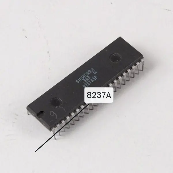
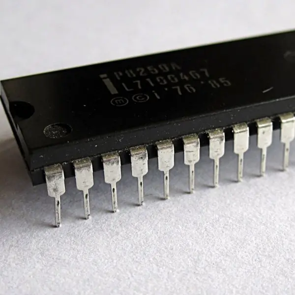
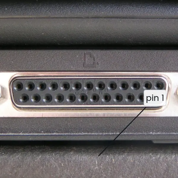
I/O is the part of a computer that students find hardest to picture, because it is about timing and who owns the bus. The plate shows the real chips and the real port that do this work.
The figures then draw the timing: a four-step handshake, one serial character bit by bit, a daisy chain choosing between two requests, the signals of a DMA transfer, three DMA modes on a bus timeline, and bit stuffing.
The numbers (bit times, character rates, stuffed strings, CPU time lost) were calculated with Python.


6.7.1 Eight applications of interrupts, DMA and serial I/O in Nepal
- Keyboard and mouse in a college lab. Each key press raises an interrupt, so the CPU runs the keyboard routine only when needed. In a Tribhuvan University computer lab, hundreds of key presses per minute cost almost no processing time. This is far better than polling the keyboard thousands of times a second.
- Disk transfers on a server. A hard disk or SSD copies whole blocks to memory by DMA. A server that stores TU EMIS records or NEPSE trade data can read many blocks while the CPU works on other requests. The CPU is interrupted once per block, not once per byte.
- Network cards at an ISP. A network card writes arriving packets into memory by DMA and interrupts the CPU after a batch. This lets a home connection from an ISP such as WorldLink carry hundreds of megabits per second on a modest CPU. Without DMA the CPU would do nothing but move bytes.
- Printers and parallel ports. Old dot-matrix printers still print forms in some offices, and they use the strobe and busy handshake of Fig. 6.1. The computer sends a character only when the printer says it is ready. Handshaking stops characters being lost when the printer is slow.
- Serial links in card and POS readers. Many card readers and barcode scanners send characters as serial frames like Fig. 6.2. A shop that accepts Fonepay QR or card payments depends on such short, reliable character frames. A parity bit lets the receiver detect a flipped bit.
- Power-fail interrupts during load-shedding. Inverters and UPS controllers watch the mains with a non-maskable interrupt, like the 8085 TRAP. When power fails, the interrupt saves data and switches to the battery in a few milliseconds. This kind of control became familiar to every Nepali household during the load-shedding years.
- Priority interrupts in embedded controllers. A weather-station logger of the Department of Hydrology and Meteorology must handle a timer, a sensor and a serial port. The daisy chain or an 8259-type controller makes sure that the most urgent device is served first. Less urgent devices wait for a few microseconds.
- Bit-oriented protocols on broadband links. Home broadband in Nepal often uses PPP over Ethernet, and PPP framing is derived from HDLC with flag bytes and bit stuffing. This keeps a frame boundary clear even if the user sends any pattern of bits. It also lets one fibre or copper line carry many different services.
Formula and fact sheet
- Asynchronous frame = 1 start + n data (+ parity) + 1–2 stop bits; chars/sec = baud ÷ bits per frame (9600/10 = 960).
- Polling wastes CPU; interrupts overlap I/O with computation; DMA bypasses the CPU for blocks.
- DMA handshake: DREQ → HOLD → HLDA → DACK; transfer; interrupt at the end.
- DMA modes: burst, cycle stealing, transparent.
- Daisy-chain: fixed priority by position (PI/PO). Parallel priority: encoder + mask register.
- 8085 interrupts: TRAP > RST 7.5 > RST 6.5 > RST 5.5 > INTR.
Chapter summary
- An interface adapts the peripheral to the CPU through data, status and control registers; I/O is isolated or memory-mapped.
- Strobe and handshake coordinate data transfer between unsynchronised units; handshake confirms delivery.
- Programmed I/O polls; interrupt-driven I/O signals; DMA moves blocks with one interrupt at the end.
- Priority is resolved by software polling, daisy chain or a priority encoder; the 8259 extends the 8085's interrupt lines.
- IOPs run their own channel programs; communication processors offload character- and bit-oriented protocols.
Practice
- Why is an interface needed between the CPU and a peripheral? List the registers of a typical interface.
- Compare memory-mapped and isolated I/O.
- Explain source-initiated strobe and handshaking; why is handshaking better?
- Compare programmed I/O and interrupt-driven I/O.
- Explain the daisy-chain priority interrupt scheme with a diagram.
- Describe the DMA transfer procedure, naming each signal.
- Differentiate the three DMA transfer modes.
- A serial line runs at 4800 baud with 1 start, 8 data, 1 parity and 2 stop bits. How many characters per second?
- What is an I/O processor? How does it differ from DMA?
- Differentiate character-oriented and bit-oriented protocols. Show bit stuffing of
0111110111111.
Answers and worked solutions
1. Different electrical/data formats, speed mismatch, word length differences, device selection. Registers: data, status, control.
2. See the table in 6.1: memory-mapped shares the address space and uses ordinary memory instructions; isolated uses a separate space and IN/OUT.
3. Source-initiated strobe: the source puts data on the bus then pulses a strobe. Handshaking adds an acknowledge from the destination, so each side knows the other's state — delivery is guaranteed whatever the speeds.
4. In programmed I/O the CPU polls the flag and is busy; in interrupt-driven I/O the device interrupts, so the CPU does useful work meanwhile.
5. Devices in series, PI/PO per device, nearest-to-CPU has the highest priority (diagram in 6.4).
6. CPU programs address/count → DREQ → HOLD → HLDA → DACK + transfers (address ++, count −−) → HOLD released → interrupt on completion.
7. Burst: whole block at once; cycle stealing: one word per stolen bus cycle; transparent: only when the CPU is not using the bus.
8. Bits per character = 1 + 8 + 1 + 2 = 12; 4800 / 12 = 400 characters per second.
9. An IOP is a processor with its own I/O instruction set that runs channel programs from memory; DMA merely moves data between memory and a device, without making decisions.
10. Character-oriented: control characters (SYN, STX, ETX) frame data; bit-oriented: flag 01111110 frames data. Stuffing 0111110111111: the data is 0 11111 0 11111 1. Insert a 0 after each group of five 1s → 0 11111 0 0 11111 0 1 = 011111001111101 (15 bits; the second group of five 1s is followed by a stuffed 0 before the final 1).
Model answers for Unit 6
Q1. Differentiate between memory-mapped I/O and isolated (I/O-mapped) I/O. (5 marks)
An I/O interface gives each peripheral one or more registers (data, status, control), and the CPU must be able to name them with an address. There are two ways to do this.
In isolated I/O the devices have their own address space, separate from memory. The CPU has a control line (IO/M on the 8085) that says whether an address means memory or a port, and it uses special instructions, IN port and OUT port.
In memory-mapped I/O the device registers occupy part of the ordinary memory address space, and the CPU reads or writes them with the same instructions it uses for memory, such as LDA, STA, MOV A,M or an ARM LDR.
| Point | Isolated I/O | Memory-mapped I/O |
|---|---|---|
| Address space | separate from memory | shared with memory |
| Instructions | special IN and OUT only |
all memory instructions |
| Control signals | separate I/O read and write | memory read and write |
| Address range | 8085: 256 ports (8-bit address) | any memory address |
| Memory lost | none | some addresses used by devices |
| Programming | limited to the accumulator on 8085 | can use arithmetic and logic on a register directly |
| Examples | 8085, x86 ports | ARM, MIPS, most microcontrollers |
Isolated I/O keeps all memory for programs and makes I/O instructions easy to spot in a listing. Memory-mapped I/O gives a richer instruction set for devices and a simpler CPU.
The 8085 supports both: IN 05H reaches port 05H, while a device placed at 8000H can be read with LDA 8000H.
Q2. Explain strobe control and handshaking in asynchronous data transfer. Why is handshaking better? (5 marks)
The CPU and a device run on different clocks, so they must agree when data on the bus is valid. This is called asynchronous data transfer.
Strobe control uses a single control line. In source-initiated strobe the source puts data on the bus and then pulses the strobe; the destination latches the data on the edge.
In destination-initiated strobe the destination pulses the strobe to ask for data and the source answers.
The weakness is that the side that did not start the transfer gives no reply: in the first scheme the source cannot know whether the destination really took the data, and in the second the destination cannot know that the data is valid.
Handshaking adds a second line so that every signal is answered.
In the source-initiated form (Fig. 6.1): (1) the source places data and raises DATA VALID; (2) the destination takes the data and raises DATA ACCEPTED; (3) the source drops DATA VALID and removes the data; (4) the destination drops DATA ACCEPTED, and the next transfer may begin.
Each side now knows the state of the other.
Handshaking is better because delivery is guaranteed whatever the speeds, a slow device never loses data and a fast one never waits more than needed.
It is used by the parallel printer port (strobe, busy, acknowledge, Plate 6.1c) and by mode 1 of the 8255 interface chip.
Q3. Explain the modes of data transfer between the CPU and I/O devices. Compare them. (10 marks)
Introduction. Peripherals are far slower than the CPU and have their own formats, so a computer needs a plan for moving data through the I/O interface. There are three modes: programmed I/O, interrupt-initiated I/O and direct memory access (DMA).
1. Programmed I/O (polling). The CPU runs a loop that reads the device's status register until the ready flag is set, and then moves one word:
loop: IN status ; ANI 01H ; JZ loop ; IN data
The hardware is simple, but the CPU does no useful work while it waits. On the 8085 each pass of this loop takes IN 10 + ANI 7 + JZ 10 = 27 T-states, about 9 microseconds at 3 MHz.
2. Interrupt-initiated I/O. The CPU does other work.
When the device is ready it raises an interrupt; the CPU finishes the current instruction, saves the PC, jumps to the interrupt service routine (ISR), moves the word, restores the state and resumes.
The 8085 pins RST 5.5, 6.5 and 7.5 jump to 002CH, 0034H and 003CH. Vectored interrupts give the address directly; non-vectored ones need polling to find the source. Several devices need a priority scheme (Fig. 6.3).
3. Direct memory access. For bulk data a DMA controller moves the block between device and memory by itself. The CPU programs the address and count, and is interrupted once at the end (Fig. 6.4).
A device at 20 KB/s sending 4096 words costs 4096 x 20 microseconds = 82 ms of CPU time by interrupts (40% of the 205 ms the block takes to arrive) but only about 2 ms of bus time by DMA.
| Point | Programmed | Interrupt-driven | DMA |
|---|---|---|---|
| Who moves each word | CPU | CPU (in the ISR) | DMA controller |
| CPU during the wait | busy-waiting | free for other work | free for other work |
| Hardware | simplest | interrupt logic | DMA controller, bus arbitration |
| Overhead per word | polling loop | save/restore, about 20 microseconds | almost none |
| CPU interrupted | never | once per word | once per block |
| Best for | trivial or very fast devices | keyboard, mouse, slow devices | disk, network, video |
Conclusion. Polling is simplest, interrupts use the CPU well for slow, occasional events, and DMA is essential for fast, bulk transfers. A real computer uses all three: interrupts for the keyboard, DMA for the disk.
Q4. Explain the daisy-chain priority interrupt scheme with a diagram. What are its advantages and disadvantages? (5 marks)
When several devices can interrupt, the system must decide who is served first. In the daisy chain, the devices are connected in series on the interrupt-acknowledge line.
Each device has a priority-in (PI) and a priority-out (PO) line, and the device nearest the CPU has the highest priority (Fig. 6.3).
Working: the CPU sends the acknowledge signal to PI of Device 1. A device that is not requesting copies PI to PO, passing the signal on.
A device that is requesting sets PO = 0, which blocks every device after it, and puts its vector address on the data bus. The CPU uses the vector to find the ISR.
In Fig. 6.3 Device 2 and Device 3 both request; Device 1 passes the signal, Device 2 keeps PO = 0 and is served, and Device 3 receives PI = 0 and waits.
Advantages: very little hardware, one acknowledge line for any number of devices, easy to add a device at the end of the chain.
Disadvantages: the priority is fixed by physical position; a low-priority device may starve; a failure in one device can break the chain; the signal must ripple through each device, so a long chain is slow.
Parallel priority hardware (a priority encoder with a mask register, or an 8259) removes these limits: the priorities can be changed and individual devices can be masked.
Q5. Explain the DMA transfer procedure and the three DMA transfer modes. (10 marks)
Introduction. In programmed and interrupt-driven I/O every word passes through the CPU.
Direct memory access (DMA) lets a DMA controller (for example the Intel 8237 of Plate 6.1a) move data directly between a device and memory, so the CPU is involved only at the start and the end.
The controller. It holds an address register (next memory address), a word count register (words left), a control register (direction and mode) and a status register.
The procedure (Fig. 6.4).
- The CPU programs the controller with the memory address, word count and direction, and then carries on with other work.
- The device raises DREQ when it has a word.
- The controller raises HOLD to ask the CPU for the buses.
- The CPU finishes its current bus cycle, tri-states its address, data and control lines and replies HLDA.
- The controller sends DACK to the device, puts the memory address on the address bus and issues the read and write strobes; the word goes directly from the device to memory. The address register is incremented and the word count decremented.
- Steps 2-5 repeat until the count is 0. The controller drops HOLD, the CPU takes the buses back, and the controller interrupts the CPU once to say the block is done.
The three modes (Fig. 6.5).
| Mode | How it takes the bus | Effect on the CPU | Speed of transfer |
|---|---|---|---|
| Burst (block) | keeps the bus for the whole block | CPU stalled for the block | fastest |
| Cycle stealing | takes one cycle per word, then returns the bus | slowed a little | medium; the usual choice |
| Transparent | uses only cycles the CPU does not need | not slowed at all | slowest, most complex |
Worked numbers. For a block of 1000 words, a 0.5 microsecond memory cycle and a device that supplies a word every 10 microseconds: burst mode holds the bus for 1000 x 0.5 = 500 microseconds at a time; cycle stealing takes 500 microseconds in 10 ms, so the CPU loses 5%; transparent mode loses nothing.
Conclusion. DMA suits fast, bulk devices such as disks and network cards. It frees the CPU, but needs extra hardware and bus arbitration, and DMA is given priority over the CPU because a device cannot wait without losing data.
Q6. A serial line uses 1 start bit, 8 data bits, even parity and 1 stop bit at 9600 baud. Draw the frame for the letter A, find the character rate, and bit-stuff the data 0111110111111. (5 marks)
Frame for A. ASCII A = 41H = 01000001. Data bits are sent least significant bit first: 1 0 0 0 0 0 1 0 (Fig. 6.2). The data contain two 1s, which is already even, so the even-parity bit is 0.
The frame is: start 0, data 1 0 0 0 0 0 1 0, parity 0, stop 1. That is 1 + 8 + 1 + 1 = 11 bits.
Character rate. One bit lasts 1/9600 = 104.17 microseconds, so one character lasts 11 x 104.17 = 1.146 ms. The rate is 9600 / 11 = 872.7 characters per second. (Without parity, 10 bits, the rate is 960 characters per second.)
Bit stuffing. In a bit-oriented protocol such as HDLC the flag is 01111110, so the sender inserts a 0 after every five consecutive 1s (Fig. 6.6). The data 0111110111111 is 0 11111 0 111111. A 0 is inserted after the first five 1s and after the next five 1s:
0 11111 0 0 11111 0 1 = 011111001111101
The 13 data bits become 15 bits. The receiver removes any 0 that follows five 1s and recovers the original data.