Unit 4 · 28 min read
Microprogrammed and Hardwired Control
What the syllabus asks for 9
- Micro-operations and control signals
- Hardwired control
- Microprogrammed control
- The microprogrammed control unit
- A microinstruction format (the Mano example)
- Symbolic and binary microprograms
- Design of the control unit
- Control of the AC register and the ALU
- Seeing the ideas: control units, microinstructions and real control words
The control unit decides which control signals fire at each clock tick. There are two ways to build it: as a fixed circuit of gates (hardwired) or as a tiny stored program called a microprogram (microprogrammed).
This unit shows both, builds a microprogram for the basic computer's fetch and ADD, and explains how a micro-sequencer picks the next microinstruction.
- Micro-operations, microinstructions, microprograms; the role of control memory.
- Hardwired versus microprogrammed control, with trade-offs.
- Control memory, address sequencing, conditional branching, mapping, subroutines.
- The microinstruction format and symbolic/binary microprograms (FETCH and ADD).
- Design of the control unit: requirements, structure, and the micro-program sequencer.
- Control of the AC register and ALU organisation.
4.1 Micro-operations and control signals
A micro-operation is one elementary register-level action done in one clock period — AR ← PC, AC ← AC + DR, PC ← PC + 1.
An instruction is carried out by a sequence of micro-operations; a control word is the set of bits that enables exactly the micro-operations of one clock period. Micro-operations are of four kinds:
- Register-transfer (
R1 ← R2). - Arithmetic (add, subtract, increment, decrement, complement).
- Logic (AND, OR, XOR, clear, complement).
- Shift (logical, arithmetic, circular).
Control signals open the paths for these actions (select a bus source, load a register, set an ALU function, read or write memory).
4.2 Hardwired control
In a hardwired control unit the control functions are implemented directly as a network of gates, decoders and flip-flops.
The basic computer of Unit 3 is hardwired: the sequence counter feeds a decoder giving T0–T15, the opcode feeds a decoder giving D0–D7, and each control signal is a Boolean expression such as LD(AC) = D0T5 + D1T5 + D2T5 + ….
Design steps: write down the micro-operations for every instruction; derive, for every control input, the Boolean function of timing, opcode and flag signals; minimise the logic; build the gates.
| Advantages | Disadvantages | |
|---|---|---|
| Hardwired | very fast — no memory lookup, only gate delays | hard to design for large instruction sets; changes mean redesign; inflexible |
4.3 Microprogrammed control
A microprogrammed control unit stores the control words in a special memory — the control memory (usually ROM; writable control stores exist too).
Each word of control memory is a microinstruction, which specifies the micro-operations of one step plus how to find the next microinstruction.
A sequence of microinstructions that implements one machine instruction is a microprogram (or routine). The microprograms for the whole instruction set together are the firmware.
Terms:
- Microinstruction — one word of control memory: control bits plus next-address information.
- Microprogram — the sequence of microinstructions for one machine instruction.
- Micro-operation — what a microinstruction causes to happen.
- Control address register (CAR) — holds the address of the microinstruction to be executed.
- Control data register (pipeline register) — holds the microinstruction being executed, letting the next one be fetched meanwhile.
| Hardwired | Microprogrammed | |
|---|---|---|
| Speed | faster | slower (a control-memory read per step) |
| Flexibility | fixed | change the microprogram, not the hardware |
| Design effort | grows steeply with instruction set | systematic, regular |
| Cost/complexity | cheaper for simple CPUs | better for complex instruction sets (CISC) |
| Typical use | RISC CPUs, simple processors | CISC processors (older x86), bug fixes by microcode update |
| Error repair | rewire | update the microcode |
Modern x86 chips combine both: a hardwired fast path for simple instructions and microcode for complex ones, and they can load microcode updates at boot.
4.4 The microprogrammed control unit
 external input (opcode, status)
        │
        ▼
 ┌─────────────┐   ┌──────────────┐   ┌──────────────────┐   ┌────────────────────┐
 │ next-address│──►│ control      │──►│ control memory   │──►│ control data       │──► control signals
 │ generator   │   │ address reg. │   │ (microprogram    │   │ register (pipeline)│    (to datapath)
 │ (sequencer) │   │ CAR          │   │  ROM)            │   │                    │
 └─────────────┘   └──────────────┘   └──────────────────┘   └────────────────────┘
        ▲                                                            │
        └──────── next-address information, condition bits ──────────┘
- The control memory holds the microprogram.
- The CAR supplies the address; the microinstruction is read into the control data register.
- The next-address generator (micro-program sequencer) computes the next CAR value from: the current CAR + 1, an address field in the microinstruction (branch), a mapped address from the machine opcode (start of a new routine), a return address from a subroutine register (SBR), or a condition test.
Address sequencing
How the next microinstruction is chosen:
| Mechanism | Next CAR |
|---|---|
| Incrementing | CAR + 1 (the default) |
| Unconditional branch | the AD field of the microinstruction |
| Conditional branch | AD if the tested condition (e.g. AC = 0, sign) is true, else CAR + 1 |
| Mapping | formed from the opcode in IR: bits 0 xxxx 00 — each opcode gets a 4-word block |
| Subroutine call/return | CALL: SBR ← CAR + 1, CAR ← AD; RET: CAR ← SBR |
A machine instruction's opcode must be converted into the start address of its microprogram. A simple map places the opcode in the middle of the CAR: with a 4-bit opcode, CAR = 0 + opcode + 00 (7 bits for a 128-word memory).
Opcode 0000 → address 0, 0001 → 4, 0010 → 8, 0011 → 12: each routine gets 4 words. A routine longer than 4 words branches to a shared area.
Conditional branching
A status-bit test selects between a branch and the next sequential address. Condition inputs include the sign of AC, AC = 0, the carry E, the I (indirect) bit and the interrupt flag.
The microinstruction names which condition to test; the sequencer multiplexer picks that bit and, if true, loads the branch address.
4.5 A microinstruction format (the Mano example)
A 20-bit microinstruction in a 128-word control memory (7-bit addresses, 128 × 20 = 2560 bits):
  3     3     3    2    2     7
┌─────┬─────┬─────┬────┬────┬────────┐
│ F1  │ F2  │ F3  │ CD │ BR │   AD   │
└─────┴─────┴─────┴────┴────┴────────┘
- F1, F2, F3 (3 bits each): three micro-operation fields; each selects one of 7 micro-operations (000 = none). Three fields mean up to three micro-operations in parallel per microinstruction, as long as they use different hardware.
- CD (condition, 2 bits): 00 = always 1 (unconditional), 01 = indirect bit I, 10 = AC sign bit, 11 = AC = 0.
- BR (branch, 2 bits): 00 JMP (jump to AD if condition = 1, else CAR + 1), 01 CALL (same, but save return address), 10 RET (CAR ← SBR), 11 MAP (CAR ← mapped opcode).
- AD (address, 7 bits): the branch address.
The micro-operation tables (symbol = what it does):
| F1 | Symbol | Micro-operation | F2 | Symbol | Micro-operation | F3 | Symbol | Micro-operation |
|---|---|---|---|---|---|---|---|---|
| 000 | NOP | none | 000 | NOP | none | 000 | NOP | none |
| 001 | ADD | AC ← AC + DR | 001 | SUB | AC ← AC − DR | 001 | XOR | AC ← AC ⊕ DR |
| 010 | CLRAC | AC ← 0 | 010 | OR | AC ← AC ∨ DR | 010 | COM | AC ← AC′ |
| 011 | INCAC | AC ← AC + 1 | 011 | AND | AC ← AC ∧ DR | 011 | SHL | AC ← shl AC |
| 100 | DRTAC | AC ← DR | 100 | READ | DR ← M[AR] | 100 | SHR | AC ← shr AC |
| 101 | DRTAR | AR ← DR(0–10) | 101 | ACTDR | DR ← AC | 101 | INCPC | PC ← PC + 1 |
| 110 | PCTAR | AR ← PC | 110 | INCDR | DR ← DR + 1 | 110 | ARTPC | PC ← AR |
| 111 | WRITE | M[AR] ← DR | 111 | PCTDR | DR(0–10) ← PC | 111 | — | unused |
Two micro-operations that need different hardware can share one microinstruction by being placed in different fields — for example READ (F2) and INCPC (F3) in the fetch routine, or ACTDR and DRTAC together, which swaps AC and DR because both transfers use the old values in the same clock period.
4.6 Symbolic and binary microprograms
A symbolic microprogram is the readable, assembly-like form, listing for each microinstruction a label, the three micro-operations, the condition, the branch type and the address.
It is translated by a microprogram assembler into the binary microprogram (the 20-bit words to burn into ROM).
The fetch routine (always at address 64)
        ORG 64
FETCH:  PCTAR            U   JMP  NEXT     ; AR ← PC
        READ, INCPC      U   JMP  NEXT     ; DR ← M[AR], PC ← PC + 1
        DRTAR            U   MAP           ; AR ← DR(0–10), then map opcode → routine
Three microinstructions (the third needs no jump label: MAP loads CAR from the opcode). U means unconditional, NEXT means the following address.
The ADD routine (opcode 0000 → address 0)
        ORG 0
ADD:    NOP              I   CALL INDRCT   ; if indirect (I = 1), call INDRCT
        READ             U   JMP  NEXT     ; DR ← M[AR]
        ADD              U   JMP  FETCH    ; AC ← AC + DR, go back to fetch

INDRCT: READ             U   JMP  NEXT     ; DR ← M[AR]
        DRTAR            U   RET           ; AR ← DR(0–10), return
Trace of ADD with direct addressing: the first microinstruction tests I (= 0, so no call), then READ loads the operand into DR, then ADD adds it to AC and jumps to FETCH (64).
With indirect addressing the CALL goes to INDRCT, which reads the pointer, loads AR, and returns to the next word.
The binary form of one line, e.g. ADD U JMP FETCH: F1 = 001 (ADD), F2 = 000, F3 = 000, CD = 00 (U), BR = 00 (JMP), AD = 1000000 (64): 001 000 000 00 00 1000000. The other routines follow the same pattern:
        ORG 4
BRANCH: NOP    S   JMP  OVER      ; S: branch if AC is negative…
        NOP    U   JMP  FETCH
OVER:   NOP    I   CALL INDRCT
        ARTPC  U   JMP  FETCH     ; PC ← AR

        ORG 8
STORE:  NOP    I   CALL INDRCT
        ACTDR  U   JMP  NEXT      ; DR ← AC
        WRITE  U   JMP  FETCH     ; M[AR] ← DR

        ORG 12
EXCHANGE: NOP  I   CALL INDRCT
        READ   U   JMP  NEXT
        ACTDR, DRTAC  U  JMP NEXT  ; swap AC and DR
        WRITE  U   JMP  FETCH
Four routines, four words each (addresses 0, 4, 8, 12) — exactly what the mapping 0 + opcode + 00 provides. The opcodes are ADD = 0000, BRANCH = 0001, STORE = 0010, EXCHANGE = 0011.
In BRANCH the condition S (AC sign) makes the first microinstruction jump to OVER when AC is negative; otherwise the second one returns to FETCH, so the branch is taken only if AC < 0.
4.7 Design of the control unit
Requirements
The control unit must (1) sequence the steps of the instruction cycle (fetch, decode, execute); (2) generate the correct control signals at the correct time; (3) react to status flags and interrupts; (4) start the right routine for each opcode.
In a microprogrammed unit requirement (4) is the mapping logic and (2) is the control memory.
Structure of the microprogrammed control unit
- Control memory (ROM, e.g. 128 × 20);
- Control address register (CAR);
- Control data register (pipeline register) holding the current microinstruction so the next can be fetched during execution;
- Sequencer — the next-address logic: multiplexer choosing among CAR + 1, AD, mapped address, SBR; a condition multiplexer driven by CD; and an incrementer;
- Decoders turning the F1, F2, F3 fields into the actual control signals for the datapath.
The design effort of a microprogrammed unit is in writing the microcode, not in routing gates, which is why it scales to large instruction sets.
The micro-program sequencer
A commercial sequencer (e.g. the AMD 2910) packages the address-selection logic: it holds the CAR, an incrementer, the SBR/stack for subroutines and loop counters, and a multiplexer with inputs "CAR + 1", "branch address", "stack/return" and "mapped".
Its inputs are the instruction field (jump/call/return/map), the condition test (pass/fail) and the branch address; its output is the next CAR. A microprogrammed control unit is therefore: sequencer + ROM + pipeline register.
4.8 Control of the AC register and the ALU
Each register is built from flip-flops with load, increment and clear inputs. The AC register gets its input from the ALU, and its control signals come from the same Tᵢ·Dⱼ products:
r = D7 I′ T3   (register-reference)      p = D7 I T3   (input-output)

LD(AC)  = D0T5 + D1T5 + D2T5 + p·B11 + r·(B9 + B7 + B6)   ; AND, ADD, LDA, INP, CMA, CIR, CIL
INR(AC) = r·B5                                            ; INC
CLR(AC) = r·B11                                           ; CLA
Here B11, B9, B7, B6, B5 are the individual bits of the instruction (CLA = bit 11, CMA = bit 9, CIR = bit 7, CIL = bit 6, INC = bit 5 — compare the codes 7800, 7200, 7080, 7040, 7020 in Unit 3).
The ALU is a combinational circuit with inputs AC, DR and INPR and outputs to AC.
Its operations (add, AND, transfer DR, transfer INPR, complement, shift right, shift left) are selected by control signals from the control unit; E receives the carry-out.
Shifts through E (CIR, CIL) are done in the AC register logic rather than the adder.
4.9 Seeing the ideas: control units, microinstructions and real control words
A control unit decides which register transfers happen in each clock pulse. It can do this with gates (hardwired) or with a small program in a ROM (microprogrammed).
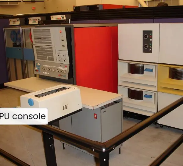
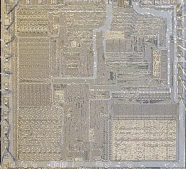
The plate shows a famous microprogrammed machine and a microcoded chip, and the figures show both designs, the 20-bit microinstruction drawn to scale, and the real binary control words of the fetch and ADD routines.
The binary words were produced by a small microassembler written for this book, using the F1, F2, F3, CD and BR tables of Section 4.5.


4.9.1 Eight advantages of microprogrammed control
- Systematic design. Every instruction becomes a short list of microinstructions written in a fixed format (Fig. 4.3). Designers fill in a table instead of drawing a different gate network for each instruction. This makes a large instruction set far easier to design correctly.
- Easy to change. To add or fix an instruction the engineer changes the words in control memory, not the wiring. The IBM System/360 family used this idea to run one instruction set on machines of different speed. A modern CPU can even receive a microcode update at start-up.
- Lower design cost. A new processor in a family can reuse the same control-unit structure (Fig. 4.2) with a different microprogram. Less new logic means fewer design errors and shorter development time. This was important when a company made many models.
- Complex instructions are possible. An instruction such as a string move or a floating-point divide needs dozens of steps. A microroutine carries them out and the programmer sees only one instruction. This is the CISC approach used by the Intel 8086 and its successors.
- Emulation and compatibility. A new machine can imitate an older one by loading the old machine's microprogram. Organisations that kept old programs running, such as banks, benefited from such compatibility. Customers did not need to rewrite their software.
- Regular, testable structure. The control memory can be read and tested word by word, and bugs can be traced to one microinstruction. Diagnostic microprograms check the datapath at power-on. This makes repair and testing simpler than hunting faults in random logic.
- Flexible subroutines. The CALL and RET fields (Section 4.5) let common steps, such as the INDRCT routine at addresses 67-68, be written once and shared by many instructions (Fig. 4.4). This keeps the control memory small. The same idea of reuse appears in ordinary programs.
- Writable control store. Some machines use RAM for the control memory, so an operating system or a researcher can load new microcode. It allows experiments with new instructions without making a new chip. The price is speed, which is why the fastest simple CPUs still use hardwired logic.
Formula and fact sheet
- Control memory 128 × 20 → 2560 bits; microinstruction = F1 (3) + F2 (3) + F3 (3) + CD (2) + BR (2) + AD (7) = 20 bits.
- Mapping: CAR = 0 + opcode(4) + 00 ⇒ opcode n → address 4n.
- Fetch routine at address 64: PCTAR; READ, INCPC; DRTAR, MAP.
- BR: 00 JMP, 01 CALL, 10 RET, 11 MAP. CD: 00 always, 01 I, 10 AC sign, 11 AC = 0.
- Hardwired = fast, inflexible; microprogrammed = flexible, slower; RISC → hardwired; CISC → microcoded.
Chapter summary
- A micro-operation is one register-level action; a microinstruction packs those of one clock period plus the next-address information; a microprogram is the routine for one machine instruction.
- Hardwired control uses gates, is fast and hard to change; microprogrammed control uses a control memory, is flexible and slower.
- The sequencer chooses the next address by increment, jump, conditional jump, opcode mapping, or subroutine return.
- Mano's 20-bit microinstruction has three micro-operation fields, a condition field, a branch field and a 7-bit address.
- FETCH is three microinstructions, and each machine instruction's routine ends by branching back to FETCH.
Practice
- Define micro-operation, microinstruction and microprogram.
- Differentiate between hardwired and microprogrammed control with advantages of each.
- Draw the block diagram of a microprogrammed control unit and describe each part.
- List the ways in which the next microinstruction address can be selected.
- What is mapping? Find the control-memory address of the routine for opcode 0011 in the Mano scheme.
- Explain the microinstruction format F1 F2 F3 CD BR AD with sizes.
- Write the symbolic microprogram for FETCH and explain every line.
- Write the ADD routine and trace it for an indirect operand.
- Why is a pipeline register used in the control unit?
- What is the function of a microprogram sequencer?
Answers and worked solutions
1. Micro-operation: a single register-transfer/arith/logic/shift action in one clock; microinstruction: a control-memory word specifying micro-operations of one step and the next address; microprogram: the sequence of microinstructions implementing a machine instruction.
2. See the table in section 4.3: hardwired is faster but inflexible and hard to design for big instruction sets; microprogrammed is regular, flexible and field-updatable but slower.
3. Sequencer → CAR → control memory → control data register → control signals, with condition/status inputs feeding the sequencer (diagram in 4.4).
4. Increment, unconditional branch, conditional branch, opcode mapping, subroutine call/return.
5. Mapping converts the opcode into the start address of its routine. Opcode 0011 → 0 0011 00 = 0001100₂ = 12.
6. F1, F2, F3 = 3 bits each (three micro-operations); CD = 2 bits (condition); BR = 2 bits (branch type); AD = 7 bits (branch address): 20 bits in total.
7. PCTAR (AR ← PC); READ, INCPC (DR ← M[AR], PC ← PC + 1 in parallel); DRTAR + MAP (AR ← DR(0–10) and CAR ← mapped opcode). The routine always lives at address 64, and each machine instruction ends by jumping back to FETCH.
8. ADD: NOP with I CALL INDRCT; READ; ADD, JMP FETCH. If I = 1, the CALL saves CAR + 1 in SBR and enters INDRCT, which reads the pointer (READ), loads AR (DRTAR) and returns (RET) to the READ word; then READ fetches the operand, ADD adds, and control returns to FETCH.
9. It holds the current microinstruction while the next one is fetched from control memory, overlapping fetch and execution of microinstructions and shortening the clock period.
10. It selects the next control-memory address — CAR + 1, branch, mapped opcode, or return address — according to the instruction field and the condition tests.
Model answers for Unit 4
Q1. Differentiate between hardwired and microprogrammed control units. (5 marks)
A hardwired control unit produces control signals with a fixed network of gates, decoders and flip-flops: the sequence counter gives T0-T15, the opcode gives D0-D7 and AND-OR logic combines them (Fig. 4.1).
A microprogrammed control unit stores the control words in a control memory; each machine instruction is carried out by a microprogram, a sequence of microinstructions read one per clock pulse (Fig. 4.2).
| Point | Hardwired | Microprogrammed |
|---|---|---|
| Method | gates, decoders, flip-flops | control memory (ROM) plus CAR and sequencer |
| Speed | faster (only gate delays) | slower (a memory read per step) |
| Flexibility | fixed; a change means redesign | change the microprogram only |
| Design effort | grows steeply with instruction set | regular, table-like |
| Complex instructions | hard | easy (CISC) |
| Cost | cheaper for small designs | cheaper for large instruction sets |
| Typical use | RISC processors, simple CPUs | older x86, IBM System/360 family |
| Error repair | rewire | microcode update |
Modern x86 chips use both: hardwired logic for common simple instructions and microcode for the complex ones.
Q2. Explain the microinstruction format of the basic computer with the meaning of each field. (5 marks)
The Mano example uses a 20-bit microinstruction in a control memory of 128 words (7-bit addresses), so the memory holds 128 x 20 = 2560 bits (Fig. 4.3). The fields are:
- F1, F2, F3 (3 bits each). Three micro-operation fields. Each selects one of seven micro-operations (000 means none), so up to three operations on different hardware happen in parallel in one clock pulse. For example F1 = 001 is ADD (AC <- AC + DR), F2 = 100 is READ (DR <- M[AR]) and F3 = 101 is INCPC (PC <- PC + 1).
- CD (2 bits). The condition to test: 00 always 1 (U), 01 the indirect bit I, 10 the sign bit of AC (S), 11 AC = 0 (Z).
- BR (2 bits). The branch type: 00 JMP, 01 CALL, 10 RET, 11 MAP.
- AD (7 bits). The branch address.
JMP goes to AD if the condition is 1, otherwise to CAR + 1. CALL does the same and saves the return address in SBR. RET loads CAR from SBR. MAP loads CAR from the opcode (0 + opcode + 00).
Real example. ADD U JMP FETCH assembles to 001 000 000 00 00 1000000 = 20040H: perform ADD, unconditional, jump to address 64.
Q3. Describe the organisation of a microprogrammed control unit with a block diagram. (10 marks)
Introduction. A microprogrammed control unit makes control signals by reading microinstructions from a control memory instead of using gates. Each machine instruction is carried out by a short microprogram stored there (Plate 4.1c, Fig. 4.2).
Parts and their roles.
- Control memory. A ROM (128 words x 20 bits in the Mano design) holding all microprograms.
- Control address register (CAR). Holds the address of the microinstruction to be read.
- Control data register (pipeline register). Holds the microinstruction being executed, so that the next address can be found while the current word controls the datapath.
- Next-address generator (sequencer). Decides the next CAR value from CD, BR and AD.
- Subroutine register SBR. Holds the return address for a CALL.
- Mapping logic. Converts the opcode of the machine instruction into the start address of its microroutine: address = 0 + opcode + 00, so each routine has room for four words.
- Datapath. AR, PC, DR, AC, ALU and the bus; its control inputs come from F1, F2 and F3, and the flags I, S and Z return to the sequencer.
- Clock. Each pulse executes one microinstruction.
Operation. The fetch routine at address 64 runs AR <- PC, then DR <- M[AR] with PC <- PC + 1 in parallel, then AR <- DR(0-10) and MAP, which loads CAR with the start of the routine for the opcode (Fig. 4.4).
The routine runs and ends with a jump back to 64. For ADD with direct addressing, six microinstructions are executed (64, 65, 66, 0, 1, 2); with indirect addressing eight, because the INDRCT subroutine at 67-68 is called from address 0.
Comparison with hardwired control. The hardwired unit (Fig. 4.1) needs different gate logic for each instruction; the microprogrammed unit needs only a different control-memory word. The cost is one memory read per step, so it is slower.
Conclusion. The microprogrammed control unit is a small computer inside the computer: CAR is its program counter, the control memory is its program memory and the sequencer is its branch logic.
This regular structure made the large instruction sets of the System/360 and the 8086 practical.
Q4. Write the fetch routine and the ADD routine of the basic computer in microprogram form and give the binary words. (5 marks)
Fetch routine (always at address 64): three microinstructions.
FETCH:  PCTAR        U  JMP NEXT     ; AR <- PC
        READ, INCPC  U  JMP NEXT     ; DR <- M[AR], PC <- PC + 1
        DRTAR        U  MAP          ; AR <- DR(0-10); CAR <- mapped opcode
ADD routine (opcode 0000, address 0) with the subroutine INDRCT:
ADD:    NOP    I  CALL INDRCT     ; if I = 1, call INDRCT
        READ   U  JMP  NEXT       ; DR <- M[AR]
        ADD    U  JMP  FETCH      ; AC <- AC + DR, back to fetch
INDRCT: READ   U  JMP  NEXT       ; DR <- M[AR]
        DRTAR  U  RET             ; AR <- DR(0-10), return
Assembled with INDRCT at address 67, the real binary words (F1 F2 F3 CD BR AD) are:
| Addr | Binary | Hex |
|---|---|---|
| 64 | 110 000 000 00 00 1000001 | C0041 |
| 65 | 000 100 101 00 00 1000010 | 12842 |
| 66 | 101 000 000 00 11 0000000 | A0180 |
| 0 | 000 000 000 01 01 1000011 | 002C3 |
| 1 | 000 100 000 00 00 0000010 | 10002 |
| 2 | 001 000 000 00 00 1000000 | 20040 |
| 67 | 000 100 000 00 00 1000100 | 10044 |
| 68 | 101 000 000 00 10 0000000 | A0100 |
With direct addressing the CD test of I fails at address 0, so the sequence is 64, 65, 66, 0, 1, 2 (six pulses). With indirect addressing it is 64, 65, 66, 0, 67, 68, 1, 2 (eight pulses), as the RET at 68 returns to address 1.
Q5. Explain address sequencing in a microprogrammed control unit. (10 marks)
Introduction. Address sequencing is the way the control unit chooses the address of the next microinstruction.
Microinstructions of one routine are stored in consecutive addresses, but the unit must also start the routine for each opcode, branch on conditions and call shared subroutines (Fig. 4.2).
The routes to the next address.
- Incrementing. The normal case is CAR <- CAR + 1. It is used when the condition is false or when no branch is needed.
- Unconditional branch.
U JMP addrloads CAR with AD. It is used to return to the fetch routine at 64. - Conditional branch. CD selects I, S or Z; if the chosen bit is 1, CAR <- AD, otherwise CAR + 1. The BRANCH routine uses S so that a machine branch is taken only when AC is negative.
- Mapping. The BR code MAP loads CAR from the opcode bits: address = 0 + opcode + 00. ADD (0000) maps to 0, BRANCH (0001) to 4, STORE (0010) to 8 and EXCHANGE (0011) to 12.
- Subroutine call. CALL saves CAR + 1 in the subroutine register SBR and jumps to AD; it is used by every routine that may be indirect, to call INDRCT.
- Subroutine return. RET loads CAR from SBR, so INDRCT returns to the instruction after the CALL.
- Initial address. On power-up, or at the end of a routine, CAR is set to 64 to start the fetch.
Summary table.
| Mode | BR code | Next CAR |
|---|---|---|
| Jump (condition true) | 00 | AD |
| Jump (condition false) | 00 | CAR + 1 |
| Call | 01 | AD, with SBR <- CAR + 1 |
| Return | 10 | SBR |
| Map | 11 | 0 + opcode + 00 |
Example. For ADD with indirect addressing the sequence is 64, 65, 66 (MAP to 0), 0 (CALL to 67, SBR = 1), 67, 68 (RET to 1), 1, 2 (JMP to 64) (Fig. 4.4).
Conclusion. The same few mechanisms, increment, jump, map, call and return, are enough to run any microprogram. Because the next address is part of every word, the control unit needs no separate program counter logic.