Unit 11 · Science and Technology · 21 min read
Electricity and Magnetism
What the syllabus asks for 6
- Ohm's law
- resistance
- electrical power
- magnetic effect of current
- electromagnetic induction
- generator and transformer
Nepal is rich in rivers, and its hydropower stations turn falling water into electricity that lights homes in Kathmandu, runs machines in Birgunj and is even sold to India. How does moving water produce electricity? Why does a heater get hot and a fan spin? How does a mobile charger turn 220 V into 5 V? The answers lie in the close relation between electricity and magnetism. In this unit you will learn Ohm's law and resistance, electrical power and energy, the magnetic effect of an electric current, electromagnetic induction, and the working of the generator and the transformer.
V = IR, resistors in series and parallel, R = \rho l/A, P = VI, energy in kWh and electricity bills, Joule's heating law, the rules (right-hand grip, Fleming's left- and right-hand rules), Faraday's law, the working of a DC motor, an AC generator and a transformer, and V_s/V_p = N_s/N_p.
Basic ideas. An electric current is the flow of electric charge (electrons in a metal wire). If a charge Q passes a point in time t, the current is
The unit of current is the ampere (A): 1 A = 1 coulomb per second. The potential difference (voltage) V between two points is the work done per unit charge in moving charge between them. Its unit is the volt (V): 1 V = 1 joule per coulomb. A cell or battery supplies the potential difference that pushes charge round a circuit. Current is measured by an ammeter connected in series; potential difference is measured by a voltmeter connected in parallel. By convention, current flows from the positive terminal to the negative terminal outside the cell, which is opposite to the direction of electron flow.
11.1 Ohm's law
At constant temperature, the current flowing through a conductor is directly proportional to the potential difference across its ends.
The constant R is the resistance of the conductor. A graph of V against I is a straight line through the origin whose slope is R. Conductors that obey Ohm's law are called ohmic (a metal wire at constant temperature). A filament lamp or a diode is non-ohmic.
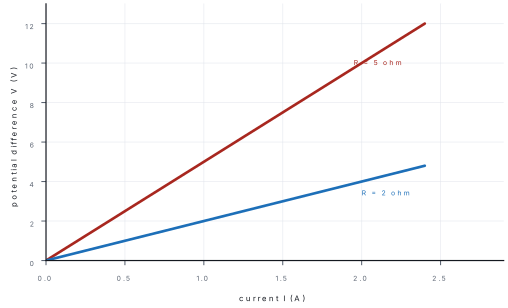
Problem. A 12 V battery is connected across a resistor of 4 Ω. Find the current. What potential difference is needed to send 0.5 A through the same resistor?
Solution. I = \dfrac{V}{R} = \dfrac{12}{4} = 3 A.
For 0.5 A: V = IR = 0.5 \times 4 = 2 V.
11.2 Resistance
Resistance is the opposition offered by a conductor to the flow of electric current through it. Its SI unit is the ohm (Ω): 1 Ω is the resistance when a potential difference of 1 V drives a current of 1 A.
Factors affecting the resistance of a wire
- Length l: R \propto l. A longer wire has more resistance.
- Cross-sectional area A: R \propto 1/A. A thicker wire has less resistance.
- Material: different materials have different resistivity.
- Temperature: the resistance of a metal rises with temperature.
Combining the first three,
where \rho is the resistivity (specific resistance) of the material, in ohm metre (Ω m). It is the resistance of a wire of unit length and unit cross-section, and depends only on the material (and temperature).
| Material | Resistivity (Ω m) | Use |
|---|---|---|
| Silver | 1.6\times10^{-8} | Best conductor, expensive |
| Copper | 1.7\times10^{-8} | Connecting wires |
| Aluminium | 2.8\times10^{-8} | Overhead power lines |
| Nichrome | 1.1\times10^{-6} | Heater coils, electric iron |
| Tungsten | 5.6\times10^{-8} | Bulb filament (high melting point) |
| Glass / rubber | 10^{10} to 10^{14} | Insulators |
Problem. Find the resistance of a nichrome wire 5 m long with cross-sectional area 0.5\ \text{mm}^2. (\rho = 1.1\times10^{-6} Ω m.)
Solution. A = 0.5\ \text{mm}^2 = 0.5\times10^{-6}\ \text{m}^2.
R = \rho\dfrac{l}{A} = \dfrac{1.1\times10^{-6} \times 5}{0.5\times10^{-6}} = 11 Ω.
Combination of resistors
Series. Resistors are joined end to end. The same current flows through each, and the total potential difference is shared.
Parallel. Resistors are connected between the same two points. The potential difference across each is the same, and the current divides.
For two resistors in parallel, R_p = \dfrac{R_1R_2}{R_1 + R_2}. The equivalent resistance in parallel is always smaller than the smallest resistor.
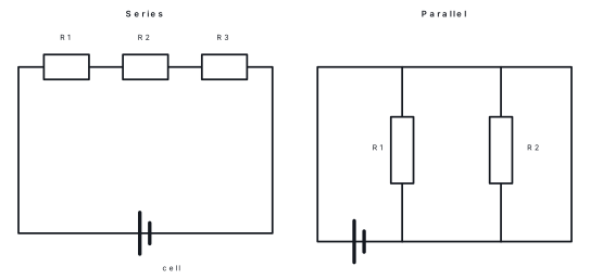
Problem. Resistors of 2 Ω, 3 Ω and 5 Ω are connected in series to a 10 V battery. Find the total resistance, the current, and the potential difference across each resistor.
Solution. R_s = 2 + 3 + 5 = 10 Ω. I = \dfrac{V}{R_s} = \dfrac{10}{10} = 1 A.
V_1 = 1 \times 2 = 2 V, V_2 = 1 \times 3 = 3 V, V_3 = 1 \times 5 = 5 V. Check: 2 + 3 + 5 = 10 V ✓.
Problem. A 6 Ω and a 3 Ω resistor are connected in parallel to a 12 V supply. Find the equivalent resistance, the total current and the current in each resistor.
Solution. \dfrac{1}{R_p} = \dfrac{1}{6} + \dfrac{1}{3} = \dfrac{1 + 2}{6} = \dfrac{1}{2}, so R_p = 2 Ω.
Total current I = \dfrac{12}{2} = 6 A.
I_1 = \dfrac{12}{6} = 2 A and I_2 = \dfrac{12}{3} = 4 A. Check: 2 + 4 = 6 A ✓.
Household appliances are connected in parallel, so that each gets the full 220 V and can be switched on or off independently. Decorative lights in older strings were in series: one failed bulb switched them all off.
11.3 Electrical power
Electrical energy and power
When a charge Q moves through a potential difference V, the work done (energy transferred) is W = QV. As Q = It,
Electrical power is the rate at which electrical energy is used:
The unit is the watt (W). 1 W = 1 J s⁻¹. Larger units: 1 kW = 1000 W, 1 MW = 10^6 W.
Commercial unit of energy
The joule is too small for household use. Electrical energy is billed in kilowatt-hours (kWh), called one unit.
Energy in kWh = power in kW \times time in hours.
Problem. A bulb is marked 100 W, 220 V. Find the current drawn and the resistance of its filament when it works normally.
Solution. I = \dfrac{P}{V} = \dfrac{100}{220} = 0.45 A.
R = \dfrac{V^2}{P} = \dfrac{220^2}{100} = \dfrac{48400}{100} = 484 Ω.
Problem. A house has 5 bulbs of 40 W used for 6 hours daily and a 1 kW heater used for 2 hours daily. Find the energy used in 30 days and the bill at Rs 10 per unit.
Solution. Bulbs: 5 \times 40 = 200\ \text{W} = 0.2 kW; energy per day = 0.2 \times 6 = 1.2 kWh.
Heater: 1 \times 2 = 2 kWh per day.
Total per day = 3.2 kWh; in 30 days = 3.2 \times 30 = 96 kWh (units).
Bill = 96 \times 10 = Rs 960.
Heating effect of current (Joule's law)
When current flows through a resistor, electrical energy changes to heat. The heat produced is
The heat produced is proportional to the square of the current, to the resistance, and to the time. Applications: electric heater, iron, toaster, kettle (nichrome wire is used, since it has high resistivity and a high melting point), bulbs (a thin tungsten filament glows white-hot), and the fuse.
A fuse is a short piece of wire of low melting point placed in series in a circuit. When the current is too large (short circuit or overload), the wire heats, melts and breaks the circuit, saving the appliances and preventing fire. A modern alternative is the miniature circuit breaker (MCB). A fuse is always put in the live wire.
Problem. A current of 2 A passes through a resistor of 50 Ω for 10 minutes. Find the heat produced.
Solution. t = 10 \times 60 = 600 s. H = I^2Rt = 2^2 \times 50 \times 600 = 4 \times 50 \times 600 = 1.2\times10^5 J.
Do not write "the bulb used 100 W". A watt is a rate (joules per second). The energy used is P \times t in J or kWh. A "unit" of electricity is 1 kWh, an amount of energy, not of power.
11.4 Magnetic effect of current
Oersted's experiment
In 1820 Hans Christian Oersted noticed that a compass needle held near a wire carrying current was deflected. When the current was reversed, the deflection was reversed. So a current-carrying conductor produces a magnetic field around it. This showed that electricity and magnetism are linked.
Magnetic field of a straight wire
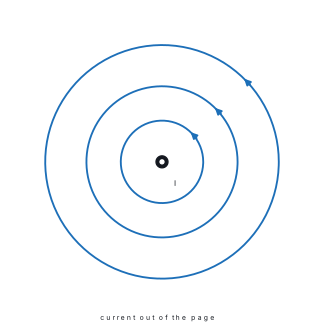
The field lines around a straight wire are concentric circles in a plane perpendicular to the wire, with the wire at the centre. Their direction is given by the right-hand grip rule: hold the wire in your right hand with the thumb pointing in the direction of the current; the curled fingers show the direction of the magnetic field. The field is stronger near the wire, and stronger when the current is larger.
Field of a solenoid and electromagnet
A solenoid is a long coil of insulated wire wound in a cylinder. When current flows, the field inside is strong and nearly uniform, parallel to the axis; outside it looks like the field of a bar magnet. One end acts as a north pole and the other as a south pole. Looking at an end, if the current flows anticlockwise it is the north pole; if clockwise it is the south pole.
An electromagnet is a solenoid with a soft iron core. Soft iron is magnetised strongly while the current flows and loses its magnetism when the current stops. The strength can be increased by:
- passing a larger current,
- using more turns of wire,
- using a soft iron core.
Uses: electric bell, crane lifting scrap iron, relay, loudspeaker, MRI machine, magnetic levitation trains.
Force on a current-carrying conductor in a magnetic field
When a conductor carrying current is placed in a magnetic field, it experiences a force (the motor effect). The force is greatest when the wire is perpendicular to the field, and zero when the wire is parallel to the field. Its size is proportional to the current, the length of wire in the field and the field strength. The direction is given by Fleming's left-hand rule:
Stretch the thumb, forefinger and middle finger of the left hand at right angles to each other. - Forefinger → direction of the magnetic field (north to south) - Centre (middle) finger → direction of the current - Thumb → direction of the thrust (force) on the conductor
DC motor
An electric motor changes electrical energy into mechanical energy. A rectangular coil is placed between the north and south poles of a magnet. Its two ends are connected to two halves of a split ring, the commutator, which touch two fixed carbon brushes joined to a battery.
- Current flows through the coil. By Fleming's left-hand rule, the forces on the two long sides are equal and opposite (one up, one down). They turn the coil.
- When the coil becomes vertical, the commutator halves swap brushes and the current in the coil is reversed, so the forces keep turning the coil in the same direction.
- The coil rotates continuously.
The speed can be increased by increasing the current, the number of turns, the strength of the magnet, or the area of the coil. Motors drive fans, washing machines, mixers, pumps and electric vehicles.
11.5 Electromagnetic induction
In 1831 Michael Faraday showed the opposite effect: a magnet can produce a current. When a bar magnet is pushed into a coil connected to a sensitive galvanometer, the needle deflects. When the magnet is pulled out, the needle deflects in the opposite direction. When the magnet is still, there is no deflection.
The production of an electromotive force (and a current in a closed circuit) in a conductor whenever the magnetic flux linked with it changes is called electromagnetic induction.
Faraday's law: the induced emf is proportional to the rate of change of magnetic flux through the circuit. So the induced emf is larger if:
- the magnet moves faster (the field changes faster),
- the magnet is stronger,
- the coil has more turns.
Lenz's law: the direction of the induced current is such that it opposes the change that produced it. (This is the law of conservation of energy: we must do work to push the magnet in.)
Stretch the thumb, forefinger and middle finger of the right hand at right angles. Thumb = direction of motion of the conductor; forefinger = direction of the field; middle finger = direction of the induced current.
Easy way to remember: left hand for motors (current in, motion out); right hand for generators (motion in, current out).
Mutual induction
When the current in one coil (primary) changes, a changing magnetic field passes through a neighbouring coil (secondary) and induces an emf in it. This is mutual induction. It works only when the current is changing, and is the principle of the transformer.
A magnet at rest inside a coil, or a steady DC current in the primary coil, induces nothing. Induction needs a change in flux. This is why a transformer works only on AC.
11.6 Generator and transformer
AC generator (dynamo)
A generator changes mechanical energy into electrical energy, using electromagnetic induction. A rectangular coil (the armature) rotates between the poles of a strong magnet. As it turns, the magnetic flux through it keeps changing, so an emf is induced. The ends of the coil are connected to two slip rings, which rub against carbon brushes that lead to the external circuit.
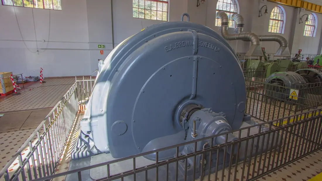
- In half a turn, the induced current flows one way; in the next half it reverses. So the output is an alternating current (AC).
- In Nepal and India, the AC supply is 220 V and 50 Hz: the current reverses direction 100 times a second.
- The output is increased by rotating the coil faster, using a stronger magnet, more turns, or a larger coil.
- If a commutator (split ring) is used in place of slip rings, the output is a pulsating direct current (DC generator).
In a hydropower station, falling water turns a turbine, which turns the coil (or magnet) of a generator. In a thermal power station, steam turns the turbine. Wind and tidal power use the same principle.
| AC | DC | |
|---|---|---|
| Direction | Changes periodically | One direction only |
| Source | AC generator | Cell, battery, solar cell |
| Transmission | Easy to step up and down by transformer; small loss | Not easily |
| Frequency | 50 Hz in Nepal | 0 |
Transformer
A transformer is a device used to increase (step up) or decrease (step down) an AC voltage. It works on mutual induction.
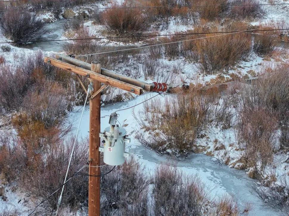
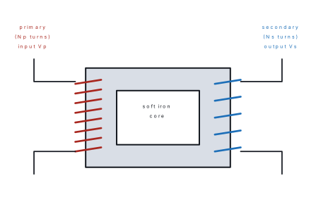
Construction: a laminated soft iron core, a primary coil (input) and a secondary coil (output), both insulated and wound on the core. Working: AC in the primary produces a changing magnetic flux in the core; the same flux links the secondary and induces an AC emf of the same frequency.
| Step-up transformer | Step-down transformer | |
|---|---|---|
| Turns | N_s > N_p | N_s < N_p |
| Output voltage | Greater than input | Less than input |
| Output current | Smaller | Larger |
| Use | Raise voltage at the power station for long-distance transmission | Mobile chargers, adapters, local supply to homes |
For an ideal transformer (no energy loss), input power equals output power:
So if the voltage is stepped up, the current is stepped down in the same ratio. A transformer works only on AC, because only a changing current produces a changing flux; with DC it will not work.
Why transmit at high voltage? For a given power P = VI, a higher voltage means a smaller current I. The heat lost in the lines is I^2R, so it falls sharply. That is why power is raised to 132 kV or 220 kV (or more) at the station, carried over long wires, and stepped down in stages near towns to 11 kV and finally 220 V for homes.
Losses in real transformers: heat in the coil wires (copper loss), eddy currents in the core (reduced by laminating the core), magnetisation loss, and leakage of flux. Efficiency = \dfrac{\text{output power}}{\text{input power}} \times 100\%, typically above 95 %.
Problem. A transformer has 2000 turns in its primary and 100 turns in its secondary. The primary is connected to a 220 V AC supply. (a) Find the output voltage. (b) If the output current is 2 A, find the input current, assuming an ideal transformer.
Solution. (a) \dfrac{V_s}{V_p} = \dfrac{N_s}{N_p}, so V_s = 220 \times \dfrac{100}{2000} = 11 V. As V_s < V_p, it is a step-down transformer.
(b) V_pI_p = V_sI_s: 220 \times I_p = 11 \times 2, so I_p = \dfrac{22}{220} = 0.1 A.
Problem. A generator gives 11 kV. A step-up transformer with 100 turns in the primary raises it to 132 kV. How many turns are in the secondary?
Solution. N_s = N_p \times \dfrac{V_s}{V_p} = 100 \times \dfrac{132}{11} = 1200 turns.
Chapter summary
- I = Q/t (A); V = work per unit charge (V). Ohm's law: V = IR at constant temperature.
- R = \rho l/A. Series: R_s = R_1 + R_2 + \cdots; parallel: \dfrac{1}{R_p} = \dfrac{1}{R_1} + \dfrac{1}{R_2} + \cdots.
- Power P = VI = I^2R = V^2/R; energy W = Pt; 1 kWh = 3.6×10⁶ J. Heat H = I^2Rt. A fuse breaks an overloaded circuit.
- A current produces a magnetic field (Oersted). Right-hand grip rule gives its direction; a solenoid with an iron core is an electromagnet.
- A conductor carrying current in a magnetic field feels a force (Fleming's left-hand rule). The DC motor uses it and a split-ring commutator.
- Electromagnetic induction: changing flux induces an emf (Faraday); its direction opposes the change (Lenz). Fleming's right-hand rule gives the direction.
- AC generator: mechanical → electrical energy, slip rings, output AC (50 Hz in Nepal).
- Transformer (AC only): \dfrac{V_s}{V_p} = \dfrac{N_s}{N_p} and V_pI_p = V_sI_s for an ideal one; high-voltage transmission reduces I^2R loss.
Practice questions
Group A — Objective (1 mark each)
- The SI unit of resistance is [1]avoltbamperecohmdwatt
- Which rule gives the direction of force on a current-carrying wire in a magnetic field? [1]aFleming's left-hand rulebFleming's right-hand rulecLenz's lawdOhm's law
- A transformer works on [1]aDC onlybAC onlycboth AC and DCdneither
- 1 kWh is equal to [1]a3.6\times10^3 Jb3.6\times10^6 Jc3.6\times10^9 Jd1000 J
- In an AC generator, the output current reverses direction because of [1]athe magnetbthe slip ringscthe rotation of the coildthe brushes
Answers to Group A
1. (c) — resistance is measured in ohm (Ω).
2. (a) — thumb force, forefinger field, middle finger current.
3. (b) — only a changing current gives a changing flux.
4. (b) — 1000 W × 3600 s.
5. (c) — as the coil rotates, each side alternately moves up and down through the field, reversing the induced current every half turn.
Group B — Short answer (2 marks each)
- State Ohm's law. [2]
- Why are household appliances connected in parallel? [2]
- What is a fuse? Where is it connected in a circuit? [2]
- State Faraday's law of electromagnetic induction. [2]
- Why is electricity transmitted at high voltage? [2]
Answers to Group B
1. At constant temperature, the current through a conductor is directly proportional to the potential difference across its ends: V = IR.
2. Each appliance receives the full supply voltage (220 V) and can be switched on or off independently of the others.
3. A fuse is a wire of low melting point that melts and breaks the circuit when the current is too large. It is connected in series with the live wire.
4. The emf induced in a circuit is proportional to the rate of change of magnetic flux linked with it.
5. At high voltage the current is small for the same power, so the heat loss I^2R in the wires is much smaller.
Group C — Long answer (4 marks each)
- Three resistors of 4 Ω, 6 Ω and 12 Ω are connected in parallel across a 12 V battery. Find the equivalent resistance and the total current. [4]
- An electric iron of 1000 W, 220 V is used for 3 hours a day. Find the energy used in 30 days and the cost at Rs 12 per unit. [4]
- Draw a labelled diagram and explain the working of an AC generator. [4]
- A step-down transformer has 1000 turns in the primary and 50 turns in the secondary. If the input voltage is 220 V, find the output voltage. If the output current is 4 A, find the input current. [4]
- Explain the working of a DC motor with the help of Fleming's left-hand rule. [4]
Answers to Group C
1. \dfrac{1}{R_p} = \dfrac{1}{4} + \dfrac{1}{6} + \dfrac{1}{12} = \dfrac{3 + 2 + 1}{12} = \dfrac{6}{12} = \dfrac{1}{2}, so R_p = 2 Ω. I = \dfrac{12}{2} = 6 A.
2. Energy per day = 1 \text{ kW} \times 3 \text{ h} = 3 kWh. In 30 days: 90 kWh. Cost = 90 \times 12 = Rs 1080.
3. Draw the coil between N and S poles, slip rings and brushes. Explain: the coil rotates, the flux changes, emf is induced; slip rings give AC; current reverses every half turn (50 Hz in Nepal).
4. V_s = 220 \times \dfrac{50}{1000} = 11 V. I_p = \dfrac{V_sI_s}{V_p} = \dfrac{11 \times 4}{220} = 0.2 A.
5. Describe the coil in the magnetic field, split-ring commutator, brushes. Forces on the two sides are opposite by the left-hand rule, which turn the coil; the commutator reverses the current each half turn, so the rotation continues in one direction.
Practise more: Science and Technology question bank