Unit 16 · Electricity and Magnetism · 9 teaching hours · 30 min read
Magnetic field
What the syllabus asks for 8
- Magnetic field lines and magnetic flux; Oersted's experiment
- Force on moving charge; Force on a conductor
- Force and Torque on rectangular coil; Moving coil galvanometer
- Hall effect
- Magnetic field of a moving charge
- Biot and Savart law and application to circular coil, long straight conductor, long solenoid
- Ampere's law and applications to long straight conductor, straight solenoid, toroidal solenoid
- Force between two parallel conductors carrying current; definition of ampere
Before 1820 electricity and magnetism were two separate sciences. Then Oersted noticed a compass needle twitch beside a current-carrying wire, and within ten years Biot, Savart and Ampère had turned that twitch into a complete theory: a moving charge makes a magnetic field, and a magnetic field pushes a moving charge. This unit is the longest in the electricity section because every motor, loudspeaker, galvanometer and Hall sensor you will ever meet is an application of those two sentences.
Two derivations appear again and again in Group C: the field of a long straight conductor (Biot–Savart or Ampère) and the torque on a rectangular coil leading to the moving-coil galvanometer. Group B favours r = mv/qB, the solenoid, and the force between parallel wires with the definition of the ampere. Learn the direction rules until they are automatic — half the marks lost in this unit are lost on a wrong direction, not a wrong number.
16.1 Magnetic field lines and magnetic flux; Oersted's experiment
A magnetic field is the region around a magnet or a current in which a magnetic force can be detected. It is a vector field \vec{B}, called the magnetic flux density, and its SI unit is the tesla (T), where 1\ \text{T} = 1\ \text{N A}^{-1}\text{m}^{-1} = 1\ \text{Wb m}^{-2}.
A magnetic field line is a line drawn so that its tangent at every point gives the direction of \vec{B} there. Their properties:
- They run from N to S outside a magnet and from S to N inside it, so every line is a closed loop — unlike electric field lines, which begin and end on charges.
- The number of lines per unit area crossing a surface at right angles measures the strength of \vec{B}: crowded lines mean a strong field.
- Two field lines never intersect. If they did, the field would have two directions at one point, which is impossible.
- Lines are in tension along their length and repel sideways — which is why unlike poles attract and like poles repel.
The magnetic flux through a surface of area A placed in a uniform field \vec{B} is the product of the area and the component of \vec{B} normal to it:
where \theta is the angle between \vec{B} and the normal to the surface. The SI unit is the weber (Wb); 1\ \text{Wb} = 1\ \text{T m}^{2}. Flux is a scalar.
Because every field line is a closed loop, every line that enters a closed surface must leave it again. Hence Gauss's law for magnetism:
The net magnetic flux through any closed surface is zero: isolated magnetic poles (monopoles) do not exist.
Oersted's experiment
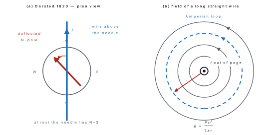
Hans Christian Oersted placed a straight wire above a pivoted compass needle and parallel to it, i.e. along the magnetic north–south line. He found:
- with no current, the needle rested along N–S;
- with a current, the needle turned through a large angle and settled almost perpendicular to the wire;
- reversing the current reversed the deflection;
- the deflection increased with the current and decreased as the wire was moved further away.
Conclusion: an electric current produces a magnetic field around it.
SNOW — current South to North in a wire Over the needle sends the N-pole West.
Right-hand grip rule — grip the wire with the right hand, thumb along the conventional current; the curled fingers give the direction of \vec{B}. This is the rule to use for every straight-wire problem.
16.2 Force on moving charge; Force on a conductor
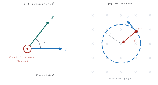
A charge q moving with velocity \vec{v} in a field \vec{B} experiences
where \theta is the angle between \vec{v} and \vec{B}.
The magnetic flux density is 1\ \text{tesla} if a charge of 1\ \text{coulomb} moving at 1\ \text{m s}^{-1} at right angles to the field experiences a force of 1\ \text{newton}.
Three consequences follow straight from F = qvB\sin\theta:
- If \vec{v} is parallel or antiparallel to \vec{B} (\theta = 0 or 180^{\circ}) the force is zero — the particle goes straight on.
- The force is greatest when \vec{v} \perp \vec{B}, and then F = qvB.
- \vec{F} is always perpendicular to \vec{v}, so the magnetic force does no work. It can change the direction of motion but never the speed or the kinetic energy.
Direction. Use Fleming's left-hand rule for the force on a positive charge (or a current): stretch the first three fingers of the left hand mutually perpendicular — Forefinger = Field, Centre finger = Current, Thumb = Thrust. For a negative charge, reverse the answer.
If a charge enters at right angles to a uniform field, the force qvB stays perpendicular to \vec{v} and constant in magnitude, so it acts as a centripetal force and the path is a circle:
The period is the circumference divided by the speed:
Notice that T and f do not contain v: fast particles simply travel round bigger circles in the same time. This is the principle of the cyclotron. If the velocity has a component along \vec{B} as well, that component is unaffected and the path becomes a helix of pitch p = v\cos\theta \cdot T.
Problem. A proton (m = 1.67\times10^{-27}\ \text{kg}, q = 1.6\times10^{-19}\ \text{C}) enters a uniform magnetic field of 0.50\ \text{T} at right angles with a speed of 2.0\times10^{6}\ \text{m s}^{-1}. Find the radius of its path, the period and the frequency of revolution.
Solution.
Force on a current-carrying conductor
A current is a stream of moving charges, so a wire in a magnetic field feels a force.
Take a straight conductor of length L and cross-sectional area A containing n free electrons per unit volume, each of charge q, drifting with speed v_d at an angle \theta to \vec{B}.
Force on one carrier: f = q v_d B \sin\theta.
Number of carriers in the length L: N = nAL.
Total force:
But the current is I = nAqv_d, so
The force is maximum (BIL) when the conductor is perpendicular to the field and zero when it lies along the field.
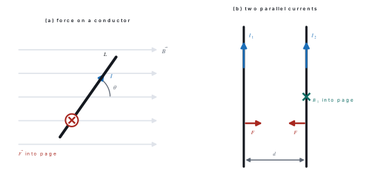
Problem. A straight wire of length 20\ \text{cm} carries a current of 5.0\ \text{A} and is placed in a uniform field of 0.40\ \text{T} so that it makes 30^{\circ} with the field. Find the force on it, and the force if the wire is turned perpendicular to the field.
Solution.
Turned perpendicular, \sin\theta = 1:
16.3 Force and Torque on rectangular coil; Moving coil galvanometer
Consider a rectangular coil of N turns, length l and breadth b, carrying a current I in a uniform field \vec{B} parallel to the plane of the coil.
The two sides of length b lie along the field, so the forces on them are zero or are equal, opposite and along the same line — they produce no turning effect.
Each side of length l is perpendicular to \vec{B}, so it carries a force
The two forces are equal and opposite but act along different lines: they form a couple. If \alpha is the angle between the plane of the coil and \vec{B}, the perpendicular distance between the two lines of action is b\cos\alpha, so
with A = lb the area of the coil. Writing \theta = 90^{\circ}-\alpha for the angle between the normal to the coil and \vec{B},
Defining the magnetic dipole moment of the coil as m = NIA (unit \text{A m}^{2}), this is simply \tau = mB\sin\theta.
- \tau is maximum = NBIA when the plane of the coil contains \vec{B} (\alpha = 0, \theta = 90^{\circ}).
- \tau is zero when the plane is perpendicular to \vec{B} (\theta = 0) — the coil is then in stable equilibrium.
- The result is independent of the shape of the coil: any plane coil of area A gives \tau = NBIA\sin\theta.
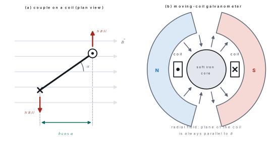
Moving coil galvanometer
Construction. A rectangular coil of many turns of fine insulated copper wire is wound on a light non-magnetic aluminium frame. It hangs by a thin phosphor-bronze suspension strip between the concave pole pieces of a strong permanent horseshoe magnet, with a cylindrical soft-iron core fixed inside it (not touching). The suspension strip carries the current in and provides the restoring couple; a fine spring below takes the current out. A small mirror on the strip and a lamp-and-scale arrangement read the deflection.
Why the field must be radial. The concave pole faces plus the soft-iron core make the field in the gap point everywhere along a radius of the cylinder. So however far the coil turns, its plane always stays parallel to \vec{B}, i.e. \theta = 90^{\circ} and \sin\theta = 1 always.
With a radial field the deflecting couple is NBIA whatever the deflection. At equilibrium it is balanced by the restoring couple c\varphi of the suspension, where c is the torsional constant (couple per unit twist):
Since N, B, A and c are all constants, \varphi \propto I: the scale is uniform. Without a radial field we would get \varphi \propto I\sin\theta and a badly cramped scale.
| Quantity | Definition | Expression |
|---|---|---|
| Current sensitivity | deflection per unit current | \varphi/I = NBA/c |
| Voltage sensitivity | deflection per unit p.d. | \varphi/V = NBA/cG |
To make a galvanometer more sensitive: increase N, A and B, and decrease c (hence phosphor bronze, which has a very small torsional constant). The soft-iron core does double duty — it makes the field radial and concentrates the flux, increasing B.
Doubling the number of turns N doubles NBA/c, but it also roughly doubles the coil resistance G, so the voltage sensitivity NBA/cG hardly changes. An instrument can be very sensitive to current and poor at detecting small p.d.s.
Problem. A rectangular coil of 100 turns and dimensions 5.0\ \text{cm} \times 4.0\ \text{cm} carries a current of 2.0\ \text{A} in a uniform field of 0.20\ \text{T}. Find the torque when (a) the plane of the coil is parallel to the field and (b) the plane makes 60^{\circ} with the field.
Solution. Area A = 0.050 \times 0.040 = 2.0\times10^{-3}\ \text{m}^{2}.
(a) Plane parallel to \vec{B} means \alpha = 0, so \cos\alpha = 1:
(b) \alpha = 60^{\circ}, so \cos 60^{\circ} = 0.50:
16.4 Hall effect
When a current-carrying conductor is placed in a magnetic field perpendicular to the current, a potential difference is set up across the conductor in the direction perpendicular to both the current and the field. This transverse p.d. is the Hall voltage V_H.
Let a slab of thickness t (measured along \vec{B}) and width w carry a current I of carriers of charge q, number density n and drift speed v_d, with \vec{B} perpendicular to I.
Step 1. Each carrier feels a magnetic force qv_dB pushing it sideways, so charge piles up on one face and the opposite charge is left on the other.
Step 2. The separated charge sets up a transverse Hall field E_H. Equilibrium is reached when the electric force balances the magnetic force:
Step 3. The Hall voltage across the width w is
Step 4. From I = nqv_dA = nqv_d(wt) we get v_d = I/(nqwt), so
The Hall coefficient is defined as R_H = 1/nq, giving V_H = R_H IB/t.
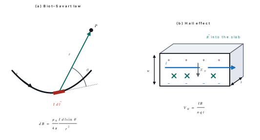
Uses of the Hall effect.
- The sign of V_H gives the sign of the charge carriers — this is how we know that conduction in an n-type semiconductor is by electrons and in a p-type by holes.
- From R_H = 1/nq we get the carrier concentration n, and hence the drift velocity.
- A calibrated slab is a Hall probe, the standard instrument for measuring magnetic flux density.
- Hall sensors count the revolutions of motors and wheels and detect whether a phone's flip cover is closed.
Problem. A copper strip of thickness 0.50\ \text{mm} carries a current of 10\ \text{A} in a magnetic field of 1.2\ \text{T} applied perpendicular to its face. If copper has n = 8.5\times10^{28}\ \text{m}^{-3} free electrons, find the Hall voltage and the Hall coefficient.
Solution.
The Hall voltage in a metal is tiny because n is enormous. In a semiconductor n is about 10^{16} times smaller, so V_H is millions of times larger — which is why Hall probes are made of semiconductors.
16.5 Magnetic field of a moving charge
A single charge q moving with velocity \vec{v} sets up a magnetic field at a point P whose position vector from the charge is \vec{r}:
where \theta is the angle between \vec{v} and \vec{r}, and
is the permeability of free space. Points to note:
- B = 0 along the line of motion (\theta = 0 or 180^{\circ}) and is greatest in the plane through the charge perpendicular to \vec{v}.
- \vec{B} is perpendicular to both \vec{v} and \vec{r}; the lines are circles centred on the line of motion — the right-hand grip rule again.
- A stationary charge (v = 0) produces no magnetic field, only an electric one.
For example, an electron moving at 2.0\times10^{7}\ \text{m s}^{-1} produces, at a point 1.0\ \text{nm} away at right angles to its motion,
— an enormous field, which is why atomic-scale magnetism is so strong.
Adding up the fields of all the carriers in a short length dl of wire, with I = nAqv_d, converts this formula into the Biot–Savart law of the next section: q\vec{v} \rightarrow I\,d\vec{l}.
16.6 Biot and Savart law and application to circular coil, long straight conductor, long solenoid
The magnetic flux density dB at a point P due to a small element of length dl of a conductor carrying current I is
where r is the distance of P from the element and \theta is the angle between the element and the line joining it to P. The direction of d\vec{B} is that of d\vec{l}\times\hat{r}, i.e. perpendicular to the plane containing the element and P.
So dB \propto I, dB \propto dl, dB \propto \sin\theta and dB \propto 1/r^{2}. The total field is found by integrating over the whole conductor.
(a) Long straight conductor
Let P be at perpendicular distance a from a straight wire. Taking an element at distance l from the foot of the perpendicular and measuring the angle \phi from that perpendicular, integration gives the standard result
where \phi_1 and \phi_2 are the angles subtended at P by the two ends. For an infinitely long wire \phi_1 = \phi_2 = 90^{\circ}, so
and for a semi-infinite wire ending at the foot of the perpendicular, B = \mu_0 I/4\pi a.
(b) Circular coil — field at the centre
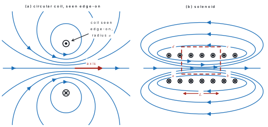
Take a circular coil of radius a carrying current I. Every element dl of the coil is perpendicular to the radius drawn to the centre, so \theta = 90^{\circ} and \sin\theta = 1, and every element is the same distance a from the centre. Also, every element contributes d\vec{B} in the same direction — along the axis — so the magnitudes simply add:
At a point on the axis at distance x from the centre the same integration gives
which reduces to \mu_0NI/2a at the centre (x = 0) and falls off as 1/x^{3} far away.
(c) Long solenoid
For a solenoid with n turns per unit length, integrating the on-axis coil formula over all the turns gives, at an axial point,
where \alpha_1 and \alpha_2 are the semi-angles subtended by the two ends. Two limits matter:
| Position | Angles | Field |
|---|---|---|
| Middle of a very long solenoid | \alpha_1 = \alpha_2 = 90^{\circ} | B = \mu_0 n I |
| At one end of a long solenoid | \alpha_1 = 0, \alpha_2 = 90^{\circ} | B = \frac{1}{2}\mu_0 n I |
Problem. (a) A circular coil of 50 turns and radius 10\ \text{cm} carries a current of 2.0\ \text{A}. Find the flux density at its centre. (b) A long straight wire carries 10\ \text{A}. Find the flux density at a point 5.0\ \text{cm} from it.
Solution.
(a)
(b)
(Using \mu_0/2\pi = 2\times10^{-7} saves a line of arithmetic every time.)
B = \mu_0 I/2\pi a is the field of a straight wire at distance a; B = \mu_0 I/2a is the field at the centre of a circular coil of radius a. They differ by a factor of \pi. Check which geometry the question describes before you write the formula.
16.7 Ampere's law and applications to long straight conductor, straight solenoid, toroidal solenoid
The line integral of \vec{B} around any closed path (an Amperian loop) equals \mu_0 times the net current threading that path:
Currents are counted positive if they are related to the sense of travel round the loop by the right-hand rule.
Ampère's law is to magnetism what Gauss's law is to electrostatics: always true, but only useful where the symmetry lets you take B outside the integral.
(a) Long straight conductor
Choose a circle of radius r centred on the wire, in the plane perpendicular to it. By symmetry B has the same magnitude everywhere on it and is everywhere tangential, so \vec{B}\cdot d\vec{l} = B\,dl:
in two lines, where Biot–Savart needed an integration. Inside a solid cylindrical conductor of radius R carrying a uniform current, the loop of radius r < R encloses only the fraction I r^{2}/R^{2}, giving
so B rises linearly from zero on the axis to \mu_0I/2\pi R at the surface, then falls as 1/r outside.
(b) Straight solenoid
Take the rectangular Amperian loop abcd of figure 5(b), with side ab = L lying along the axis inside the solenoid and side cd well outside it. Split the integral into four parts:
- along ab (inside, \vec{B} parallel to d\vec{l}): contributes BL;
- along bc and da: \vec{B} is perpendicular to d\vec{l} where the path is inside, and B \approx 0 outside, so each contributes zero;
- along cd (outside a long solenoid, where B \approx 0): contributes zero.
So \oint \vec{B}\cdot d\vec{l} = BL. The number of turns threading the loop is nL, each carrying I, so I_{enc} = nLI and
The result contains neither L nor the position of the loop inside the solenoid: the field inside a long solenoid is uniform and depends only on the turns per unit length and the current.
(c) Toroidal solenoid
A toroid is a solenoid bent into a ring of N turns. Take a circular Amperian loop of radius r running along the middle of the core. By symmetry B is constant and tangential along it, and the loop is threaded by all N turns:
Writing n = N/2\pi r for the turns per unit length along the core recovers B = \mu_0 n I. For a loop drawn inside the hole or outside the toroid, the enclosed current is zero, so B = 0 there: a toroid confines its field completely inside the windings — which is why transformer and inductor cores are toroidal.
Problem. A solenoid 50\ \text{cm} long has 500 turns and carries 3.0\ \text{A}. Find the flux density (a) at its centre and (b) at one end. (c) The same wire is wound into a toroid of mean radius 15\ \text{cm} with 500 turns and the same current; find the flux density along the mean circle.
Solution. Turns per unit length n = 500/0.50 = 1000\ \text{m}^{-1}.
(a)
(b) At the end the field is half that value: B = 1.88\times10^{-3}\ \text{T}.
(c)
16.8 Force between two parallel conductors carrying current; definition of ampere
Two long parallel wires a distance d apart carry currents I_1 and I_2.
Wire 1 produces at the position of wire 2 a field
which is perpendicular to wire 2. A length L of wire 2 therefore feels
By Newton's third law wire 1 feels an equal and opposite force. Applying Fleming's left-hand rule shows that
- currents in the same direction attract, and
- currents in opposite directions repel
Two like charges repel, but two like currents attract. Students mix these up constantly. Remember it as: parallel wires pull together, anti-parallel wires push apart.
One ampere is that steady current which, when maintained in each of two infinitely long straight parallel conductors of negligible circular cross-section placed 1\ \text{metre} apart in vacuum, produces a force of 2\times10^{-7}\ \text{newton} per metre of length between them.
Check it: with I_1 = I_2 = 1\ \text{A} and d = 1\ \text{m},
A modern footnote. Since 20 May 2019 the ampere has been defined instead by fixing the elementary charge at e = 1.602176634\times10^{-19}\ \text{C}, so that 1\ \text{A} is the current corresponding to 1/e elementary charges per second. As a result \mu_0 is now a measured quantity, though it still equals 4\pi\times10^{-7}\ \text{T m A}^{-1} to within a few parts in 10^{10}. NEB papers still ask for the force-based definition above.
Problem. Two long parallel wires 10\ \text{cm} apart carry currents of 5.0\ \text{A} and 10\ \text{A} in the same direction. Find the force per metre between them, and the total force on a 2.0\ \text{m} length. State whether it is attractive or repulsive. Where on the line joining them is the resultant field zero?
Solution.
On 2.0\ \text{m}: F = 2.0\times10^{-4}\ \text{N}, attractive, because the currents are in the same direction.
Between the wires the two fields oppose. At a distance x from the 5\ \text{A} wire,
so x = 0.0333\ \text{m} = 3.33\ \text{cm} from the 5\ \text{A} wire.
Chapter summary
- Magnetic flux \Phi = BA\cos\theta (weber); field lines are closed loops, so \oint\vec{B}\cdot d\vec{A} = 0 — there are no magnetic monopoles.
- Oersted: a current produces a magnetic field. Direction by the right-hand grip rule (or SNOW).
- Force on a moving charge \vec{F} = q\vec{v}\times\vec{B}, F = qvB\sin\theta; it does no work. Perpendicular entry gives a circle with r = mv/qB, T = 2\pi m/qB, independent of speed.
- Force on a conductor F = BIL\sin\theta; direction by Fleming's left-hand rule.
- Torque on a coil \tau = NBIA\sin\theta = NBIA\cos\alpha, with dipole moment m = NIA. A radial field makes \sin\theta = 1, so a moving-coil galvanometer has \varphi = (NBA/c)I and a uniform scale.
- Hall effect: V_H = IB/nqt with R_H = 1/nq; it gives the sign and the concentration of the carriers.
- Biot–Savart: dB = (\mu_0/4\pi)(I\,dl\sin\theta/r^{2}). Results: straight wire \mu_0I/2\pi a; centre of a coil \mu_0NI/2a; on the axis \mu_0NIa^{2}/2(a^{2}+x^{2})^{3/2}; long solenoid \mu_0nI (half that at an end).
- Ampère: \oint\vec{B}\cdot d\vec{l} = \mu_0I_{enc}, which gives the straight wire, the solenoid (\mu_0nI) and the toroid (\mu_0NI/2\pi r, zero outside) in a few lines each.
- Parallel wires: F/L = \mu_0I_1I_2/2\pi d; like currents attract. This force defines the ampere as 2\times10^{-7}\ \text{N m}^{-1} for 1\ \text{A} at 1\ \text{m}.
Practice questions
Group A — Multiple choice (1 mark each)
- The SI unit of magnetic flux is [1]ateslabweberchenrydampere-metre
- A charged particle moves parallel to a uniform magnetic field. The magnetic force on it is [1]aqvBbzerocqvB\sin 45^{\circ}dmaximum
- A charged particle enters a uniform magnetic field at right angles to it. Its path is [1]aa straight lineba parabolaca circleda helix
- The magnetic flux density at the centre of a circular coil of N turns and radius a carrying a current I is [1]a\mu_0NI/2\pi ab\mu_0NI/2ac\mu_0NI/4\pi ad\mu_0NIa
- Two long parallel wires carry currents in the same direction. They [1]aattract each otherbrepel each othercexert no forcedrotate about each other
- The magnetic flux density inside a very long solenoid of n turns per metre carrying current I is [1]a\mu_0nI/2b\mu_0nIc\mu_0nI/2\pidzero
- The field of a moving-coil galvanometer is made radial so that [1]athe coil does not rotatebthe deflection is proportional to the currentcthe coil resistance is reduceddthe torque is zero
- The Hall voltage of a slab of thickness t is proportional to [1]atb1/tct^{2}d\sqrt{t}
Answers to Group A
1. (b) — \Phi = BA\cos\theta, measured in weber = T m².
2. (b) — \sin 0^{\circ} = 0, so F = qvB\sin\theta = 0.
3. (c) — the force stays perpendicular to v and constant, so it is centripetal.
4. (b) — B = \mu_0NI/2a; the 2\pi form belongs to a straight wire.
5. (a) — like currents attract.
6. (b) — Ampère's law on a rectangular loop gives B = \mu_0nI.
7. (b) — with \sin\theta = 1 always, \varphi = (NBA/c)I, a uniform scale.
8. (b) — V_H = IB/nqt.
Group B — Short answer (5 marks each)
- Define magnetic flux and state its SI unit. Describe Oersted's experiment and state the conclusion drawn from it. [5]
- Starting from the force on a single moving charge, derive the expression F = BIL\sin\theta for the force on a current-carrying conductor in a magnetic field. [5]
- An electron (m = 9.1\times10^{-31}\ \text{kg}, e = 1.6\times10^{-19}\ \text{C}) moves at 3.0\times10^{7}\ \text{m s}^{-1} at right angles to a magnetic field of 0.20\ \text{T}. Find the radius of its path and its period of revolution. [5]
- State the Biot–Savart law and use it to find the magnetic flux density at the centre of a circular coil of N turns and radius a carrying current I. [5]
- Explain the Hall effect and show that V_H = IB/nqt. A metal strip of thickness 1.0\ \text{mm} with n = 5.0\times10^{28}\ \text{m}^{-3} carries 20\ \text{A} in a field of 1.5\ \text{T}; find the Hall voltage. [5]
- Two long parallel wires 20\ \text{cm} apart carry currents of 10\ \text{A} and 15\ \text{A} in opposite directions. Find the force per metre between them and state its nature. Hence define the ampere. [5]
Answers to Group B
3.
5. Derivation as in §16.4. Numerically, nq = (5.0\times10^{28})(1.6\times10^{-19}) = 8.0\times10^{9}, so
6.
The currents are opposite, so the force is repulsive. Definition of the ampere: see §16.8.
Group C — Long answer (8 marks each)
- (a) State the Biot–Savart law and use it to derive the magnetic flux density at a perpendicular distance a from a long straight conductor carrying a current I. [5](b) A long straight wire carries 20\ \text{A}. Find the flux density 10\ \text{cm} from it. A circular coil of 100 turns and radius 10\ \text{cm} carries 2.0\ \text{A}; find the flux density at its centre. [3]
- (a) Derive an expression for the torque on a rectangular coil carrying a current in a uniform magnetic field. Explain, with a diagram, why the field of a moving-coil galvanometer is made radial and show that its scale is uniform. [5](b) A galvanometer coil of 200 turns and area 2.0\times10^{-4}\ \text{m}^{2} hangs in a radial field of 0.20\ \text{T}. The torsional constant of the suspension is 1.0\times10^{-6}\ \text{N m} per degree. Find the deflection produced by 5.0\ \text{mA} and the current sensitivity. [3]
- (a) State Ampère's circuital law and apply it to find the magnetic flux density inside a long straight solenoid and inside a toroidal solenoid. [5](b) A toroid of mean radius 15\ \text{cm} has 500 turns and carries 3.0\ \text{A}. Find the flux density along its mean circle and the flux density outside the toroid. [3]
Answers to Group C
1. (b) Straight wire:
Circular coil:
2. (b)
Current sensitivity = \dfrac{NBA}{c} = \dfrac{(200)(0.20)(2.0\times10^{-4})}{1.0\times10^{-6}} = 8.0\times10^{3} degrees per ampere, i.e. 8 degrees per milliampere.
3. (b)
Outside the toroid (and in the central hole) the Amperian loop encloses no net current, so B = 0.
Practise more: Physics question bank