Unit 19 · Electricity and Magnetism · 6 teaching hours · 17 min read
Alternating Currents
What the syllabus asks for 6
- Peak and rms value of AC current and voltage
- AC through a resistor, a capacitor and an inductor
- Phasor diagram
- Series circuits containing combination of resistance, capacitance and inductance
- Series resonance; quality factor
- Power in AC circuits: power factor
The supply from the Nepal Electricity Authority is a sine wave of 230 V, 50 Hz — its direction reverses one hundred times every second. With a steady current, a circuit is described by one number, the resistance. With an alternating current, a capacitor and an inductor also obstruct the flow, and they do it out of step with the voltage. This unit gives you the tools for that: r.m.s. values, reactance, phasors, impedance, resonance and the power factor.
Almost every paper contains a series LCR numerical — find Z, then I, then the phase angle and the power. Group C asks you to derive the impedance from a phasor diagram and then discuss resonance and the quality factor. Learn the two mnemonics for phase (CIVIL: in a Capacitor I leads V, V leads I in an L) and never add reactances to resistances arithmetically.
19.1 Peak and rms value of AC current and voltage
An alternating current reverses direction periodically. The commonest form is sinusoidal:
where I_0 and V_0 are the peak (maximum or amplitude) values, \omega = 2\pi f is the angular frequency and f = 1/T.
The average value over a full cycle is zero, because the current spends half the cycle positive and half negative. Averaging over half a cycle gives a useful number:
But the quantity that a meter reads, and the one that matters for heating, is the root-mean-square value.
The r.m.s. value of an alternating current is that steady direct current which would produce the same heating effect in a given resistor in the same time.
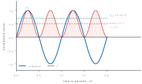
The instantaneous power dissipated in a resistance R is p = i^{2}R. Over one period the mean square current is
The cosine averages to zero over a whole number of cycles, leaving
The same argument for the voltage gives V_{rms} = V_0/\sqrt{2}.
| Quantity | Relation to peak value |
|---|---|
| r.m.s. value | I_{rms} = I_0/\sqrt{2} = 0.707\,I_0 |
| Mean over half cycle | I_{av} = 2I_0/\pi = 0.637\,I_0 |
| Mean over full cycle | 0 |
| Form factor | I_{rms}/I_{av} = 1.11 |
A "230 V" supply is 230 V r.m.s. Its peak is V_0 = 230\sqrt{2} = 325\ \text{V}, and insulation must withstand that. Unless a question says "peak" or "maximum", every a.c. voltage and current quoted is an r.m.s. value.
Problem. An alternating current is given by i = 14.14\sin(314\,t)\ \text{A}. Find (a) the peak value, (b) the r.m.s. value, (c) the frequency and period, and (d) the mean value over half a cycle.
Solution. Comparing with i = I_0\sin\omega t: I_0 = 14.14\ \text{A} and \omega = 314\ \text{rad s}^{-1}.
(a) I_0 = 14.14\ \text{A}.
(b)
(c)
(d)
19.2 AC through a resistor, a capacitor and an inductor
Take the applied voltage as v = V_0\sin\omega t in each case.
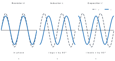
Pure resistor. By Ohm's law the current follows the voltage instant by instant:
Current and voltage are in phase; the phase difference is zero and the opposition is simply R.
Pure inductor. The only voltage in the circuit is the back e.m.f., so v = L\,di/dt:
So the current lags the voltage by \pi/2 (a quarter cycle), and the peak current is I_0 = V_0/\omega L. The quantity
is the inductive reactance, measured in ohms. It is zero for d.c. (f = 0) and grows with frequency — an inductor is a low-pass element, which is why a choke controls a.c. without wasting energy.
Pure capacitor. The charge is q = Cv = CV_0\sin\omega t, so
The current leads the voltage by \pi/2, with I_0 = \omega CV_0. The quantity
is the capacitive reactance in ohms. It is infinite for d.c. (a capacitor blocks direct current) and falls as frequency rises.
| Element | Opposition | Phase of i relative to v | Behaviour with f |
|---|---|---|---|
| Resistor R | R (ohm) | in phase | independent of f |
| Inductor L | X_L = 2\pi f L | lags by 90^{\circ} | increases with f |
| Capacitor C | X_C = 1/2\pi f C | leads by 90^{\circ} | decreases with f |
19.3 Phasor diagram
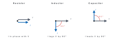
Adding sine functions of different phase by trigonometry is slow. Instead each sinusoid is represented by a phasor: a rotating vector whose length is the peak (or r.m.s.) value and which rotates anticlockwise with angular velocity \omega. The projection of the phasor on the vertical axis gives the instantaneous value.
Because every phasor in a circuit rotates at the same \omega, the angles between them stay fixed, and the diagram can be drawn frozen at t = 0. Sinusoids of the same frequency then add like vectors — by the parallelogram or triangle rule.
19.4 Series circuits containing combination of resistance, capacitance and inductance
In a series circuit the current is the same everywhere, so the current phasor is drawn first and the three voltage phasors are set against it: V_R along the current, V_L ahead of it by 90^{\circ} and V_C behind it by 90^{\circ}. Since V_L and V_C are opposite, they subtract.
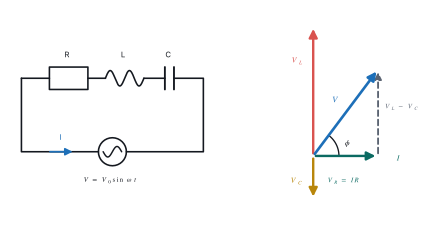
Let the common current be I (r.m.s.). The three voltage magnitudes are
V_L and V_C are in antiphase, so their resultant has magnitude |V_L - V_C| and is perpendicular to V_R. By Pythagoras,
Hence the impedance Z = V/I is
and the current lags the voltage by the phase angle \phi where
- If X_L > X_C: \phi > 0, the circuit is inductive and the current lags.
- If X_L < X_C: \phi < 0, the circuit is capacitive and the current leads.
- If X_L = X_C: \phi = 0, the circuit behaves as pure resistance — resonance.
Dropping one element gives the special cases Z = \sqrt{R^2+X_L^2} for an LR circuit and Z = \sqrt{R^2+X_C^2} for a CR circuit.
Z \ne R + X_L + X_C. Resistance and reactance are at right angles on the phasor diagram, so they combine by Pythagoras. In the same way the voltmeter readings V_R, V_L and V_C do not add up to the supply voltage — V_L alone can be far larger than V.
Problem. A resistor of 30\ \Omega, an inductor of 0.191\ \text{H} and a capacitor of 159\ \mu\text{F} are connected in series across a 220\ \text{V}, 50\ \text{Hz} supply. Find the reactances, the impedance, the current, the phase angle, and the voltage across each element.
Solution. \omega = 2\pi f = 2\pi(50) = 314.2\ \text{rad s}^{-1}.
Since X_L > X_C the current lags the voltage by 53.1^{\circ}.
Check: \sqrt{132^{2}+(264-88)^{2}} = \sqrt{17424+30976} = \sqrt{48400} = 220\ \text{V}. Note that V_L alone exceeds the supply voltage.
19.5 Series resonance; quality factor
A series LCR circuit is in resonance when the inductive and capacitive reactances are equal, so that the impedance is a minimum (Z = R), the current is a maximum (I_{\max} = V/R) and the current is exactly in phase with the applied voltage.
Setting X_L = X_C:
At resonance the circuit behaves as a pure resistance and draws maximum power. Because a large current flows, the voltages across L and C can be very much larger than the supply — they are equal and opposite and cancel each other. For this reason the series resonant circuit is called an acceptor circuit, and it is used to tune a radio receiver to one station.
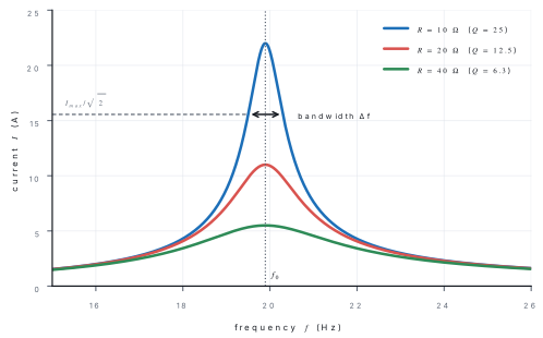
The sharpness of the peak is measured by the quality factor:
where the bandwidth \Delta f = f_2 - f_1 is the range of frequencies over which the current stays above I_{\max}/\sqrt{2}. Equivalently, Q is the factor by which the voltage across L (or C) at resonance exceeds the supply voltage: Q = V_L/V. A large Q means a sharp, selective circuit.
Problem. A series circuit has L = 2.0\ \text{H}, C = 32\ \mu\text{F} and R = 10\ \Omega, connected to a 220\ \text{V} variable-frequency supply. Find (a) the resonant angular frequency and frequency, (b) the current at resonance, (c) the quality factor, (d) the voltage across the inductor at resonance, and (e) the bandwidth.
Solution.
(a)
(b) At resonance Z = R, so
(c)
(d)
The capacitor voltage is V_C = I/\omega_0C = 22/(125\times32\times10^{-6}) = 5500\ \text{V} as well — equal and opposite, so they cancel. Note V_L/V = 5500/220 = 25 = Q, as expected.
(e)
19.6 Power in AC circuits: power factor
With v = V_0\sin\omega t and i = I_0\sin(\omega t - \phi), the instantaneous power is
Using 2\sin A\sin B = \cos(A-B) - \cos(A+B),
Averaged over a complete cycle the second term vanishes, so
The factor \cos\phi is the power factor of the circuit:
The product V_{rms}I_{rms} is the apparent power, measured in volt-ampere (VA); P_{av} is the true power in watts.
| Circuit | \phi | Power factor | Average power |
|---|---|---|---|
| Pure resistance | 0 | 1 | V_{rms}I_{rms} |
| Pure inductance | -90^{\circ} | 0 | zero |
| Pure capacitance | +90^{\circ} | 0 | zero |
| Series LCR | \tan^{-1}\frac{X_L-X_C}{R} | R/Z | V_{rms}I_{rms}\cos\phi |
| LCR at resonance | 0 | 1 | V^{2}/R |
A current that flows with \cos\phi = 0 delivers no net energy at all: energy is stored in the field for a quarter cycle and returned in the next. This is called wattless current, and it is why a choke coil is preferred to a rheostat for controlling a.c. — the choke limits current without dissipating heat.
Industries are charged for apparent power, so a low power factor is expensive. A factory in Balaju with many induction motors (inductive load, \cos\phi perhaps 0.6) connects large capacitors in parallel to cancel the lagging current and push the power factor towards 1.
Problem. A coil connected to a 200\ \text{V}, 50\ \text{Hz} supply draws a current of 5.0\ \text{A} and consumes 600\ \text{W}. Find its impedance, resistance, inductive reactance, inductance and power factor. What capacitance in series would make the power factor unity?
Solution.
True power P = I^{2}R, so
For unity power factor we need X_C = X_L = 32\ \Omega:
Chapter summary
- For i = I_0\sin\omega t: I_{rms} = I_0/\sqrt{2} = 0.707I_0, I_{av} (half cycle) = 2I_0/\pi = 0.637I_0, and the full-cycle mean is zero. Meters read r.m.s.
- Resistor: i in phase with v. Inductor: i lags by 90^{\circ}, X_L = 2\pi fL. Capacitor: i leads by 90^{\circ}, X_C = 1/2\pi fC.
- A phasor is a vector of length equal to the peak (or r.m.s.) value, rotating at \omega; sinusoids of the same frequency add like vectors.
- Series LCR: Z = \sqrt{R^{2}+(X_L-X_C)^{2}} and \tan\phi = (X_L-X_C)/R; V = \sqrt{V_R^{2}+(V_L-V_C)^{2}}.
- Resonance: X_L = X_C, so f_0 = 1/2\pi\sqrt{LC}, Z_{\min} = R, I_{\max} = V/R and \phi = 0 (acceptor circuit).
- Quality factor Q = \omega_0L/R = (1/R)\sqrt{L/C} = f_0/\Delta f = V_L/V; a large Q means a sharp resonance and a narrow bandwidth.
- Power: P_{av} = V_{rms}I_{rms}\cos\phi, with power factor \cos\phi = R/Z. Pure L or C consumes no power — wattless current.
Practice questions
Group A — Multiple choice (1 mark each)
- The r.m.s. value of the current i = I_0\sin\omega t is [1]aI_0bI_0/2cI_0/\sqrt{2}d2I_0/\pi
- In a purely capacitive a.c. circuit, the current [1]ais in phase with the voltagebleads the voltage by 90^{\circ}clags the voltage by 90^{\circ}dleads by 45^{\circ}
- At series resonance the impedance of an LCR circuit is [1]amaximum and equal to X_Lbzerocminimum and equal to Rdequal to X_L+X_C
- The average power consumed in one cycle by a pure inductor is [1]aV_{rms}I_{rms}bV_{rms}I_{rms}/2cV_0I_0dzero
- The quality factor of a series resonant circuit is [1]aR/\omega_0Lb\omega_0L/Rc\omega_0 CRd\Delta f/f_0
Answers to Group A
1. (c) — the mean of \sin^2\omega t over a cycle is \frac12.
2. (b) — i = \omega CV_0\sin(\omega t+\pi/2).
3. (c) — X_L - X_C = 0, so Z = \sqrt{R^2+0} = R.
4. (d) — \phi = 90^{\circ}, so \cos\phi = 0 and energy is only stored and returned.
5. (b) — equivalently 1/\omega_0CR or f_0/\Delta f.
Group B — Short answer (5 marks each)
- Define the r.m.s. value of an alternating current and show that I_{rms} = I_0/\sqrt{2} for a sinusoidal current. [5]
- Derive an expression for the current when an alternating voltage V_0\sin\omega t is applied to a pure inductor. Show that the current lags the voltage by \pi/2 and define inductive reactance. [5]
- A 100\ \Omega resistor, a 0.50\ \text{H} inductor and a 10\ \mu\text{F} capacitor are joined in series across a 200\ \text{V}, 50\ \text{Hz} supply. Calculate the impedance and the current. [5]
- What is meant by the power factor of an a.c. circuit? Explain what is meant by a wattless current, and state why a choke coil is preferred to a resistor for controlling alternating current. [5]
- A series circuit has L = 0.50\ \text{H}, C = 20\ \mu\text{F} and R = 10\ \Omega. Find the resonant frequency and the quality factor. [5]
Answers to Group B
3. \omega = 314.2\ \text{rad s}^{-1}. X_L = 314.2\times0.50 = 157.1\ \Omega; X_C = 1/(314.2\times10\times10^{-6}) = 318.3\ \Omega. So X_L - X_C = -161.2\ \Omega and
The circuit is capacitive, so the current leads the voltage.
4. Outline: the power factor is \cos\phi = R/Z = true power / apparent power. A wattless (idle) current is one flowing at \cos\phi = 0, as in a pure L or C: energy is stored for a quarter cycle and returned in the next, so the net power over a cycle is zero. A choke limits the current by its reactance X_L, which consumes no power, whereas a resistor would waste the same energy as heat.
5.
\omega_0 = 1/\sqrt{LC} = 1/(3.162\times10^{-3}) = 316.2\ \text{rad s}^{-1}, so
Group C — Long answer (8 marks each)
- (a) Draw the phasor diagram for a series LCR circuit carrying an alternating current and hence derive expressions for its impedance and the phase angle between the current and the applied voltage. [4](b) What is series resonance? Obtain an expression for the resonant frequency, sketch the variation of current with frequency for two different resistances, and define the quality factor. [4]
- An inductor of 0.20\ \text{H} with negligible resistance, a 100\ \Omega resistor and a 50\ \mu\text{F} capacitor are connected in series across a 220\ \text{V}, 50\ \text{Hz} supply. Calculate(a) the impedance,(b) the current,(c) the phase angle,(d) the power factor and(e) the power dissipated. [8]
Answers to Group C
1. Outline: (a) draw I along the reference direction with V_R along I, V_L at +90^{\circ} and V_C at -90^{\circ}; the resultant gives V = I\sqrt{R^2+(X_L-X_C)^2}, so Z = \sqrt{R^2+(X_L-X_C)^2} and \tan\phi = (X_L-X_C)/R. (b) Resonance is the condition X_L = X_C, giving f_0 = 1/2\pi\sqrt{LC}, Z = R and I_{\max} = V/R; sketch the curves of §19.5 showing a sharper peak for smaller R; Q = \omega_0L/R = f_0/\Delta f.
2. \omega = 2\pi(50) = 314.2\ \text{rad s}^{-1}.
(a) X_L - X_C = 62.8 - 63.7 = -0.83\ \Omega, so
(b) I = 220/100.0 = 2.2\ \text{A}.
(c) \tan\phi = -0.83/100 = -0.0083, so \phi = -0.48^{\circ} — the current leads very slightly, because the supply is almost exactly at the resonant frequency (f_0 = 1/2\pi\sqrt{0.20\times50\times10^{-6}} = 50.3\ \text{Hz}).
(d) \cos\phi = R/Z = 100/100.0 \approx 1.00.
(e) P = I^{2}R = (2.2)^{2}\times100 = 484\ \text{W}.
Practise more: Physics question bank