Unit 18 · Electricity and Magnetism · 6 teaching hours · 18 min read
Electromagnetic Induction
What the syllabus asks for 6
- Faraday's laws; Induced electric fields
- Lenz's law; Motional electromotive force
- A.C. generators; Eddy currents
- Self-inductance and mutual inductance
- Energy stored in an inductor
- Transformer
In 1831 Michael Faraday showed that a changing magnetic field drives a current. That discovery is why power generated at Kulekhani can be stepped up to 220 kV, carried across the country and stepped back down for your house. Two laws run the whole unit: Faraday's, which gives how big the induced e.m.f. is, and Lenz's, which gives which way it drives current.
Group C asks for one of three derivations: motional e.m.f. e = Blv, the generator equation e = NBA\omega\sin\omega t, or the transformer turns-ratio with its losses. Group B likes solenoid self-inductance, U = \frac{1}{2}LI^{2} and numericals on e = -N\,d\Phi/dt. Never drop the minus sign — it is Lenz's law.
18.1 Faraday's laws; Induced electric fields
Move a magnet towards a coil joined to a galvanometer and the needle deflects. Stop the magnet and the needle returns to zero even though the magnet is still there. Move it away and the needle deflects the other way. What matters is not the flux but the rate of change of flux.
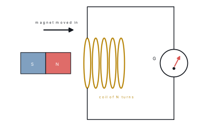
First law. Whenever the magnetic flux linked with a circuit changes, an e.m.f. is induced in it; the e.m.f. lasts only as long as the change lasts.
Second law. The magnitude of the induced e.m.f. is directly proportional to the rate of change of flux linkage:
The product N\Phi is called the flux linkage, measured in weber-turns.
Since \Phi = BA\cos\theta, the linkage changes if B changes, if A changes, or if the coil turns. All three are used in real machines.
If the circuit has total resistance R, the induced current is I = e/R and the charge that flows in a change is independent of how fast the change happens:
Induced electric fields. A stationary coil in a changing field has charges that are not moving, so no magnetic force acts on them. Something else must push them — a changing magnetic field creates an electric field in the space around it, even where there is no wire:
This induced field is non-conservative: its line integral round a closed loop is not zero, so no potential can be defined for it.
Problem. A coil of 200 turns and area 300\ \text{cm}^{2} is placed with its plane perpendicular to a magnetic field. The field increases uniformly from 0.20\ \text{T} to 0.60\ \text{T} in 0.40\ \text{s}. The coil has a resistance of 12\ \Omega. Find (a) the induced e.m.f., (b) the induced current and (c) the charge that circulates.
Solution. A = 300\ \text{cm}^{2} = 3.0\times10^{-2}\ \text{m}^{2} and \theta = 0, so \Phi = BA.
(a)
(b)
(c)
18.2 Lenz's law; Motional electromotive force
The induced current always flows in such a direction that it opposes the change in flux that produced it.
In the figure below, the N-pole of a magnet approaches a coil. The flux through the coil towards the right is increasing, so the induced current flows so as to make the near face of the coil a north pole, which repels the approaching magnet. Pull the magnet away and the current reverses, the near face becomes a south pole, and the coil tries to hold the magnet back.
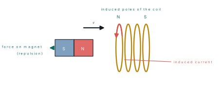
Lenz's law is conservation of energy in disguise. If the induced current helped the magnet, the magnet would accelerate by itself while the coil also got hot — energy from nothing. Because the coil pushes back, the work you do moving the magnet reappears as electrical energy. That is what the minus sign in e = -N\,d\Phi/dt says.
Motional e.m.f.
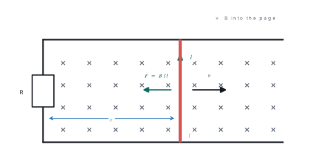
A conducting rod of length l slides with speed v on frictionless rails in a uniform field B perpendicular to the plane of the rails. After time t the enclosed area is A = lx, so the flux is \Phi = Blx. Then
so the magnitude of the e.m.f. is \boxed{e = Blv}.
By the force on the charges. A free charge in the rod moves at speed v, so it feels a force qvB along the rod. Charge separates until the electric field balances it, qE = qvB, giving E = vB and e = El = Blv — the same answer.
Energy check. The induced current is I = Blv/R, and the field exerts a retarding force F = BIl = B^{2}l^{2}v/R on the rod. The mechanical power needed to keep it moving is
which is exactly the electrical power dissipated. No energy is created.
If the rod moves at an angle \theta to the field, only the perpendicular component counts and e = Blv\sin\theta.
Problem. A rod of length 0.50\ \text{m} slides on rails at 4.0\ \text{m s}^{-1} in a uniform field of 0.80\ \text{T} perpendicular to the plane of the rails. The circuit resistance is 2.0\ \Omega. Find the e.m.f., the current, the force needed to keep the rod moving uniformly, and the power supplied. Verify that the power supplied equals the heat produced.
Solution.
Heat produced: I^{2}R = (0.80)^{2}\times2.0 = 1.28\ \text{W}. The two agree, as Lenz's law requires.
e = -N\,d\Phi/dt. The sign carries the whole physical content of Lenz's law, so state the signed form first and take magnitudes only afterwards.
18.3 A.C. generators; Eddy currents
An a.c. generator (dynamo) converts mechanical energy into electrical energy by rotating a coil in a magnetic field. Its parts are an armature (a coil of N turns wound on a soft-iron core), a field magnet, two slip rings and two carbon brushes.
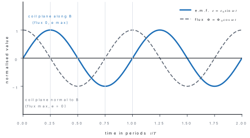
Let the coil of N turns and area A rotate with constant angular velocity \omega in a uniform field B. If the normal to the coil makes angle \theta = \omega t with \vec{B}, the flux linked is
By Faraday's law,
So e = e_0\sin\omega t with peak e.m.f. e_0 = NBA\omega = 2\pi f NBA.
The e.m.f. is maximum when the coil's plane is parallel to the field (lines are cut fastest) and zero when it is perpendicular, even though the flux is then greatest. A split-ring commutator in place of the slip rings gives a d.c. generator.
Eddy currents
When a solid block of metal sits in a changing magnetic field, the induced e.m.f. drives swirling closed loops of current through the metal. These are eddy currents. The resistance of a solid block is tiny, so the currents are large, the I^2R heating is wasteful, and by Lenz's law they oppose the motion that produced them.
| Eddy currents as a nuisance | Eddy currents put to work |
|---|---|
| Heat and energy loss in transformer and motor cores | Induction furnace for melting metals |
| Damping and heating in dynamo armatures | Induction cooker / induction heating |
| Reduced efficiency of chokes | Electromagnetic braking in trains and treadmills |
| — | Dead-beat galvanometers and speedometers |
| — | Induction-type energy meters |
They are reduced by laminating the core: varnished silicon-steel sheets stacked with their planes parallel to the flux. This breaks the large eddy loops into many small high-resistance ones, so the loss falls sharply.
18.4 Self-inductance and mutual inductance
Self-inductance. A changing current in a coil changes its own flux, which induces an e.m.f. in the same coil opposing the change — a back e.m.f. For a coil with no ferromagnetic core, the flux linkage is proportional to the current:
The self-inductance L of a coil is the flux linkage per unit current, L = N\Phi/I; equivalently it is the back e.m.f. per unit rate of change of current. Its SI unit is the henry (H): a coil has a self-inductance of one henry if a current changing at 1\ \text{A s}^{-1} induces a back e.m.f. of 1\ \text{V}. Thus 1\ \text{H} = 1\ \text{Wb A}^{-1} = 1\ \text{V s A}^{-1}.
For a solenoid of length l, cross-sectional area A and N turns carrying a current I, the interior field is B = \mu_0 nI with n = N/l. The flux through one turn is \Phi = BA = \mu_0 nIA, so the flux linkage is
With a core of relative permeability \mu_r this becomes L = \mu_0\mu_r N^{2}A/l.
Notice L depends only on the geometry of the coil and the core material — never on the current.
Mutual inductance. If a changing current I_1 in coil 1 links flux through a nearby coil 2, an e.m.f. appears in coil 2:
M is the mutual inductance, also measured in henry. For two coaxial solenoids of the same length l and area A,
It is reciprocal (M_{12} = M_{21}) and related to the self-inductances by
where the coefficient of coupling k lies between 0 and 1; k \to 1 for coils wound on a common closed iron core, as in a transformer.
18.5 Energy stored in an inductor
While the current in an inductor is growing, the source must work against the back e.m.f. e = -L\,dI/dt. In time dt the work done is
Integrating from zero current to the final current I,
This work is not dissipated — it is stored in the magnetic field, and it comes back when the current is switched off:
Energy density. For a solenoid, L = \mu_0n^{2}Al and B = \mu_0nI, so I = B/\mu_0 n and
Since Al is the volume, the energy stored per unit volume of the field is
Problem. An air-cored solenoid is 50\ \text{cm} long, has a cross-sectional area of 4.0\ \text{cm}^{2} and 1000 turns. Find (a) its self-inductance, (b) the energy stored when it carries 2.0\ \text{A}, and (c) the average induced e.m.f. if this current is switched off in 10\ \text{ms}.
Solution. l = 0.50\ \text{m}, A = 4.0\times10^{-4}\ \text{m}^{2}, N = 1000.
(a)
so L \approx 1.0\ \text{mH}.
(b)
(c)
18.6 Transformer
A transformer changes an alternating voltage to another value at the same frequency, by mutual induction. A primary of N_p turns and a secondary of N_s turns share a laminated soft-iron core, so nearly all the primary's flux also threads the secondary.
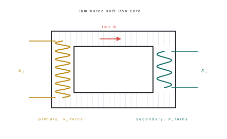
Let \Phi be the flux through each turn of the core at time t. The same d\Phi/dt acts on both coils, so
Dividing,
where k is the turns ratio. If k > 1 the transformer steps up; if k < 1 it steps down.
For an ideal (100% efficient) transformer, input power equals output power:
So voltage is stepped up only at the cost of current, and vice versa.
| Energy loss | Cause | Minimised by |
|---|---|---|
| Copper loss | I^{2}R heating in the windings | thick, low-resistance copper wire |
| Eddy-current loss | induced currents in the core | laminated, varnished core sheets |
| Hysteresis loss | repeated remagnetisation of the core | soft core with a narrow loop (silicon steel) |
| Flux leakage | flux that misses the secondary | interleaved windings on a closed core |
| Humming (magnetostriction) | core vibrating at 2f | tight clamping of laminations |
Efficiency is \eta = P_{\text{out}}/P_{\text{in}}, typically 96–99%. High-voltage transmission pays because the same power at ten times the voltage needs one-tenth the current and so wastes one-hundredth the I^{2}R heat in the line.
Problem. A step-down transformer at a substation in Hetauda converts 11\ \text{kV} to 220\ \text{V}. The primary has 5000 turns, and the secondary supplies 20\ \text{A}. Find (a) the number of secondary turns, (b) the output power, and (c) the primary current if the efficiency is 80\%.
Solution.
(a)
(b)
(c)
The 1100\ \text{W} difference is lost as heat in the copper and the core.
Chapter summary
- Faraday: an e.m.f. appears whenever flux linkage changes, e = -N\,d\Phi/dt; the charge circulated is q = N\Delta\Phi/R, independent of the time taken.
- A changing \vec{B} produces a non-conservative induced electric field, \oint\vec{E}\cdot d\vec{l} = -d\Phi/dt.
- Lenz: the induced current opposes the change producing it — a statement of energy conservation, carried by the minus sign.
- Motional e.m.f. e = Blv (or Blv\sin\theta); the retarding force is B^{2}l^{2}v/R and Fv = I^{2}R.
- A.C. generator: \Phi = BA\cos\omega t gives e = NBA\omega\sin\omega t with peak value e_0 = NBA\omega.
- Eddy currents are reduced by laminating cores; they are used in induction furnaces, induction cookers and electromagnetic brakes.
- L = N\Phi/I, e = -L\,dI/dt, solenoid L = \mu_0\mu_rN^{2}A/l; M = k\sqrt{L_1L_2} and e_2 = -M\,dI_1/dt. Unit: henry.
- Energy stored U = \frac{1}{2}LI^{2}; energy density u = B^{2}/2\mu_0.
- Transformer: E_s/E_p = N_s/N_p and, if ideal, I_s/I_p = N_p/N_s. Losses are copper, eddy-current, hysteresis, leakage and humming.
Practice questions
Group A — Multiple choice (1 mark each)
- Lenz's law is a direct consequence of the conservation of [1]achargebmomentumcenergydmagnetic flux
- The SI unit of self-inductance, the henry, is equivalent to [1]aWb A⁻¹bWb AcA Wb⁻¹dV A⁻¹
- Eddy currents in a transformer core are reduced by [1]ausing thicker wireblaminating the corecusing a steel coredincreasing the frequency
- In a step-up transformer, compared with the primary the secondary has [1]amore turns and larger currentbmore turns and smaller currentcfewer turns and larger currentdfewer turns and smaller current
- A coil of self-inductance L carries a current I. The energy stored is [1]aLI^{2}b\frac{1}{2}LI^{2}c\frac{1}{2}L^{2}IdLI
Answers to Group A
1. (c) — if the induced current aided the change, energy would be created from nothing.
2. (a) — from L = N\Phi/I, henry = weber per ampere.
3. (b) — laminations break the large eddy loops into small high-resistance ones.
4. (b) — E_s/E_p = N_s/N_p and E_pI_p = E_sI_s, so a higher voltage means a lower current.
5. (b) — from W = \int LI\,dI.
Group B — Short answer (5 marks each)
- State Faraday's laws of electromagnetic induction and define magnetic flux linkage. Show that the charge induced in a circuit is independent of the time in which the flux change occurs. [5]
- Derive an expression for the motional e.m.f. induced in a rod of length l moving with velocity v perpendicular to a uniform field B, and show that the mechanical power supplied equals the heat produced. [5]
- A coil of 100 turns and area 0.050\ \text{m}^{2} lies with its plane perpendicular to a uniform field of 0.20\ \text{T}. It is turned through 180^{\circ} in 0.10\ \text{s}. Calculate the average induced e.m.f. [5]
- Define self-inductance and derive an expression for the self-inductance of a long air-cored solenoid. [5]
- What are eddy currents? Give two useful applications and two ways in which they are a nuisance, and state how they are minimised. [5]
Answers to Group B
1. Outline: state both laws, define flux linkage N\Phi (weber-turns). For the charge, I = e/R = (N/R)(d\Phi/dt), so q = \int I\,dt = N\Delta\Phi/R — it contains no t, so a slow change gives a small current for a long time and a fast change a large current for a short time, with the same total charge.
3. Initially \Phi_1 = BA\cos0^{\circ} = 0.20\times0.050 = 0.010\ \text{Wb}; after turning, \Phi_2 = BA\cos180^{\circ} = -0.010\ \text{Wb}. So \Delta\Phi = -0.020\ \text{Wb} and
5. Outline: circulating induced currents set up in the body of a conductor in a changing field. Useful: induction furnace, induction cooker, electromagnetic braking, dead-beat galvanometer. Nuisance: heating and loss in transformer cores and motor armatures. Minimised by laminating the core with varnished silicon-steel sheets parallel to the flux.
Group C — Long answer (8 marks each)
- (a) State Lenz's law and describe an experiment to verify it. Show that it follows from the principle of conservation of energy. [4](b) Describe the construction of an a.c. generator and derive an expression for the instantaneous e.m.f. it produces. [4]
- (a) Explain the principle and working of a transformer and derive the relation between the voltages and the numbers of turns. List its energy losses and how each is reduced. [4](b) A transformer steps 240\ \text{V} down to 12\ \text{V}. The primary has 1200 turns, and the secondary delivers 5.0\ \text{A} to a lamp. Assuming the transformer is 90% efficient, find the number of secondary turns, the output power and the primary current. [4]
Answers to Group C
1. Outline. (a) State the law; use the magnet-and-coil experiment of §18.2 — pushing the N-pole in makes the near face a north pole (repulsion), withdrawing it makes that face a south pole (attraction). Energy argument: an aiding current would accelerate the magnet and heat the coil, creating energy from nothing. (b) Armature, field magnet, slip rings, brushes; \Phi = BA\cos\omega t gives e = NBA\omega\sin\omega t, peak e_0 = NBA\omega.
2. (b) N_s = N_p(E_s/E_p) = 1200\times(12/240) = 60 turns.
Practise more: Physics question bank