Chapter 14 · Current Electricity and Magnetism · 3 questions in the paper · 38 min read
Current Electricity and Thermoelectricity
What the syllabus asks for 4
- Ohm's law and Joule's law; resistance, resistivity, emf, potential difference, energy and power
- Resistors in series and parallel; Kirchhoff's laws
- Wheatstone bridge, metre bridge and potentiometer; a galvanometer converted to an ammeter and a voltmeter
- Seebeck and Peltier effects; the thermocouple
Current Electricity and Magnetism is the third-heaviest area of the Physics paper: 9 of the 50 questions (official MEC weightage), and we estimate about 3 come from this chapter. The marks are unusually predictable — a resistance or power calculation, a two-loop Kirchhoff network, a metre-bridge or potentiometer reading, a galvanometer conversion, and one fact about the thermocouple. Almost every question is a formula applied once, so the chapter rewards precision rather than insight: the right formula, the right units, the right sign.
- I = nAev_d, R = \rho L/A, and how \rho changes with temperature (positive for metals, negative for semiconductors).
- emf against terminal pd: V = E - Ir; the V–I graph has intercept E and slope -r.
- P = VI = I^2R = V^2/R; H = I^2Rt; 1 kWh = 3.6\times10^6 J and the electricity bill.
- Series and parallel rules; cells in series, in parallel and in mixed rows.
- Kirchhoff's two laws on a two-loop network, with consistent signs.
- Wheatstone balance P/Q = R/S; metre bridge R/S = l/(100-l); potentiometer E \propto l.
- Shunt S = I_gG/(I-I_g) for an ammeter; multiplier R = V/I_g - G for a voltmeter.
- Seebeck and Peltier effects; neutral temperature \theta_n and inversion temperature \theta_i = 2\theta_n - \theta_c.
14.1 Ohm's law and Joule's law; resistance, resistivity, emf, potential difference, energy and power
14.1.1 Electric current, drift velocity and current density
Electric current is the rate of flow of charge through a cross-section: I = Q/t, measured in amperes (1 A = 1 C s⁻¹). By convention the direction of current is the direction in which positive charge would flow, opposite to the motion of the electrons in a metal.
The electrons do not travel along the wire at the speed of the current. They move at a slow drift velocity v_d (typically 10^{-4} m s⁻¹, a fraction of a millimetre per second) superimposed on a much faster random motion. The lamp lights the instant you close the switch because the electric field is set up along the wire at nearly the speed of light, and every electron starts drifting almost at once.
If a conductor has n free electrons per unit volume, cross-section A, and drift velocity v_d, then in time t the charge crossing a section is neAv_dt, so
J is the current density, a vector, measured in A m⁻². Current itself is a scalar: it has a sense of flow but adds algebraically at a junction.
Why the drift is slow but steady. The field accelerates each electron, but collisions with the vibrating lattice randomise the motion. The average time between collisions is the relaxation time \tau, and the drift speed settles at
so the mobility is \mu = v_d/E = e\tau/m.
14.1.2 Ohm's law
At constant temperature, the current through a metallic conductor is directly proportional to the potential difference across it: V = IR, where R is the resistance in ohms (Ω).
The law is not universal. It holds for metals at constant temperature, but fails for a filament lamp (whose temperature rises), for a diode, for electrolytes and for thermistors. Those are called non-ohmic conductors, and their I–V graphs are curved.
| Graph | Shape for an ohmic conductor | What the slope gives |
|---|---|---|
| V against I | straight line through the origin | resistance R |
| I against V | straight line through the origin | conductance 1/R |
Resistance R = V/I depends on the material, the length, the cross-section and the temperature. Conductance G = 1/R is measured in siemens (S).
14.1.3 Resistivity
For a uniform conductor of length L and cross-section A,
where \rho is the resistivity (or specific resistance), a property of the material alone, measured in Ω m. Resistivity does not change when a wire is cut, stretched or bent; the resistance does.
Setting up. A wire of length L, area A, carrying current I under a field E = V/L.
Step 1 — current in terms of drift speed. I = nAev_d.
Step 2 — drift speed in terms of the field. v_d = eE\tau/m.
Step 3 — substitute and put E = V/L.
Step 4 — compare with V = IR and R = \rho L/A.
Result. \rho = m/(ne^2\tau) and \sigma = 1/\rho = ne^2\tau/m.
What it means. Resistivity is high when there are few carriers (n small) or short collisions (\tau small). In a metal, heating increases the lattice vibration, shortens \tau, and so raises \rho.
| Material (approximate, at room temperature) | \rho / Ω m | Class |
|---|---|---|
| Silver | 1.6\times10^{-8} | conductor |
| Copper | 1.7\times10^{-8} | conductor |
| Aluminium | 2.8\times10^{-8} | conductor |
| Nichrome | 1.0\times10^{-6} | alloy, heating element |
| Manganin, constantan | \approx 5\times10^{-7} | alloy, standard resistor |
| Germanium | \approx 0.6 | semiconductor |
| Glass | 10^{10}–10^{14} | insulator |
A wire stretched to twice its length (volume unchanged) has half the area, so R = \rho L/A becomes 4R — the resistance goes up four times, while \rho is unchanged. Cut into n equal parts, each part has R/n; joined all in parallel they give R/n^2.
14.1.4 How resistance changes with temperature
where \alpha is the temperature coefficient of resistance, in K⁻¹.
| Material | Sign of \alpha | Reason |
|---|---|---|
| Metals (Cu, Al, W) | positive, about 4\times10^{-3} K⁻¹ | heating shortens \tau; \rho = m/(ne^2\tau) rises |
| Alloys (manganin, constantan, nichrome) | almost zero | used for standard resistors and shunts |
| Semiconductors (Ge, Si), carbon | negative | heating frees many more carriers, so n rises faster than \tau falls |
Because manganin's resistance barely changes with temperature, it is wound into standard resistance coils, shunts and the wire of a potentiometer.
14.1.5 emf, potential difference and internal resistance
The electromotive force (emf) E of a source is the work done by the source in carrying unit positive charge round the complete circuit. It is measured in volts but it is not a force. The potential difference between two points is the work done per unit charge in carrying charge between those points through the external circuit.
A real cell has an internal resistance r, so part of its emf is spent inside the cell:
| Situation | Terminal pd |
|---|---|
| Open circuit (I = 0) | V = E |
| Discharging through R | V = E - Ir, always less than E |
| Being charged by a stronger source | V = E + Ir, greater than E |
| Short circuit (R = 0) | V = 0, I = E/r (the largest possible current) |
Rearranging gives the internal resistance from two measurements:
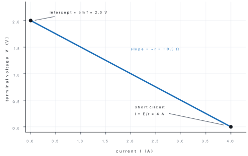
Maximum power transfer. The power delivered to the external resistor is P = I^2R = E^2R/(R+r)^2, which is greatest when R = r. Then P_{max} = E^2/(4r), the terminal voltage is E/2, and the efficiency is only 50 % — half the energy is wasted inside the cell.
14.1.6 Joule's law, power and the electricity bill
When current flows through a resistance, the electrical energy is converted into heat. Joule's law:
and the power (energy per second) is
| Quantity | Unit | Note |
|---|---|---|
| Energy | joule (J) | 1 J = 1 W s |
| Power | watt (W) | 1 kW = 1000 W |
| Commercial unit | kilowatt-hour (kWh) | 1 kWh = 3.6\times10^6 J = 1 "unit" |
The electricity meter measures energy, not power. A 100 W lamp left on for 10 h uses 1 kWh — one unit.
Problem. A 1500 W water heater runs 4 hours a day for 30 days. If NEA charges Rs 11 per unit, what is the cost?
Solution. Energy = 1.5\ \text{kW}\times4\ \text{h}\times30 = 180 kWh = 180 units. Cost = 180\times11 = Rs 1980. In joules the same energy is 180\times3.6\times10^6 = 6.48\times10^8 J.
A 60 W and a 100 W bulb are both rated for 220 V. Their resistances are R = V^2/P, so the 60 W bulb has the larger resistance. In series the same current passes through both, and P = I^2R makes the 60 W bulb glow brighter. In parallel, each gets the full 220 V and the 100 W bulb is brighter. Never assume the higher-wattage bulb is always the brighter one.
In series the current is common, so use P = I^2R (power \propto R). In parallel the voltage is common, so use P = V^2/R (power \propto 1/R). This one choice settles almost every "which bulb is brighter" question.
14.2 Resistors in series and parallel; Kirchhoff's laws
14.2.1 Series and parallel combinations
| Series | Parallel | |
|---|---|---|
| Connection | end to end | all left ends joined, all right ends joined |
| Same through each | current | potential difference |
| Adds | voltages: V = V_1 + V_2 + \dots | currents: I = I_1 + I_2 + \dots |
| Equivalent | R_s = R_1 + R_2 + \dots | \frac{1}{R_p} = \frac{1}{R_1} + \frac{1}{R_2} + \dots |
| Two resistors | R_1 + R_2 | \frac{R_1R_2}{R_1+R_2} (product over sum) |
| n equal resistors | nR | R/n |
| Result | larger than the biggest | smaller than the smallest |
Current division between two parallel resistors: I_1 = I\dfrac{R_2}{R_1+R_2} — the larger share goes through the smaller resistance.
Adding any resistor in parallel gives the current another route, so the equivalent resistance falls — it can never rise. A common distractor offers "increases because another resistor is added".
14.2.2 Cells in series and in parallel
| Arrangement | Current through R | Best when |
|---|---|---|
| n cells in series (aiding) | I = \dfrac{nE}{R + nr} | R \gg r |
| n cells in parallel | I = \dfrac{E}{R + r/n} | R \ll r |
| m rows of n cells (mixed) | I = \dfrac{nE}{R + nr/m} | R = nr/m gives the maximum |
In the mixed grouping the current is greatest when the external resistance equals the total internal resistance of the battery, R = nr/m. Series connection raises the emf; parallel connection lowers the internal resistance; mixed grouping does both.
If one cell is reversed, the total emf becomes (n-2)E, not nE. Read the polarity in the diagram before adding emfs.
Problem. Eight cells, each of emf 1.5 V and internal resistance 0.5 Ω, are joined in 2 rows of 4 and connected to a 1 Ω resistor. Find the current.
Solution. Here n = 4, m = 2:
All eight in series the current would be 12/(1+4) = 2.4 A; all eight in parallel, 1.5/(1+0.5/8) \approx 1.4 A. The mixed arrangement beats both because it raises the emf and lowers the internal resistance at the same time.
14.2.3 Kirchhoff's laws
Junction rule. The sum of the currents entering a junction equals the sum of the currents leaving it — conservation of charge. Loop rule. The algebraic sum of the potential changes round any closed loop is zero — conservation of energy.
Sign convention (fix it once and keep it):
| Move | Change |
|---|---|
| Across a resistor with the current | -IR |
| Across a resistor against the current | +IR |
| Across a cell from - to + | +E |
| Across a cell from + to - | -E |
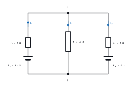
Problem. In the figure, E_1 = 12 V with r_1 = 1\ \Omega; E_2 = 6 V with r_2 = 1\ \Omega; the middle resistor is R = 4\ \Omega. Find the current in each branch.
Solution. Take I_1 upward in the left branch, I_2 upward in the right branch, and I_3 downward through R.
Junction A: I_3 = I_1 + I_2.
Left loop (through R, then the 12 V cell):
Right loop:
Substituting I_3: 5I_1 + 4I_2 = 12 and 4I_1 + 5I_2 = 6. Subtracting gives I_1 - I_2 = 6, and then I_2 = -2 A, I_1 = 4 A, I_3 = 2 A.
Reading the signs. The minus sign on I_2 means the current in the right branch actually flows downward: the 12 V cell forces 2 A backwards through the 6 V cell, so the 6 V cell is being charged. The pd across R is I_3R = 8 V.
Power check. Supplied: 12\times4 = 48 W. Used: 4^2(1) = 16 W in r_1, 2^2(1) = 4 W in r_2, 2^2(4) = 16 W in R, and 6\times2 = 12 W charging the 6 V cell. Total 48 W. ✓
For a network with one unknown, use series–parallel reduction. For two or more unknowns, label the currents and write one junction equation plus one loop equation per independent loop. Always finish by checking the power balance — it catches a sign error in seconds.
14.3 Wheatstone bridge, metre bridge and potentiometer; a galvanometer converted to an ammeter and a voltmeter
14.3.1 The Wheatstone bridge
Four resistances P, Q, R, S form a quadrilateral ABCD; a galvanometer joins B to D and a cell joins A to C. The bridge is balanced when the galvanometer shows no deflection:
Setting up. At balance the galvanometer carries no current, so B and D are at the same potential.
Step 1 — no current through the galvanometer means the current I_1 through P continues through Q, and the current I_2 through R continues through S.
Step 2 — equal potentials at B and D.
Step 3 — write each drop as IR.
Step 4 — divide the first equation by the second.
Result. The bridge balances when the ratio of the two resistances on one side equals the ratio on the other.
What it means. At balance no current flows through the galvanometer, so the measurement does not disturb the network. The condition contains only ratios, so it is unaffected by the emf of the cell, and interchanging the cell and the galvanometer leaves it unchanged. The bridge is most sensitive when all four resistances are of the same order.
14.3.2 The metre bridge
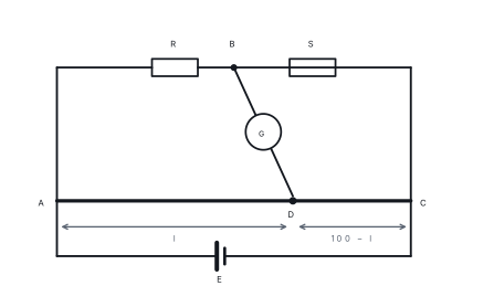
The metre bridge is a practical Wheatstone bridge. A one-metre uniform wire AC carries the two ratio arms as lengths: the unknown resistance R is in the left gap, a known resistance S in the right gap, and a jockey slides along the wire to find the balance point at length l from A.
Since the resistance of a uniform wire is proportional to its length, the two lower arms have resistances in the ratio l : (100-l), so
- The balance point should be near the middle of the wire; there the bridge is most sensitive. A balance point at 5 cm or 95 cm gives a poor measurement, and the remedy is to change S.
- The wire must be uniform and the contacts clean; end corrections allow for the resistance of the copper strips at the ends.
- The jockey must be tapped, not dragged, or the wire is scraped and its cross-section changes.
Problem. With a 6 Ω resistor in the right gap, the balance point is 40 cm from the left end. Find the resistance in the left gap.
Solution. R = S\dfrac{l}{100-l} = 6\times\dfrac{40}{60} = 4\ \Omega. The unknown is smaller than the standard, so its balance length is the shorter one — a quick check on the answer.
14.3.3 The potentiometer
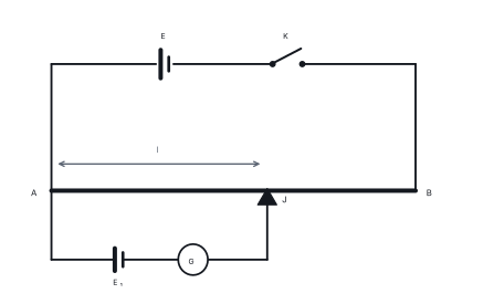
A steady current from a driver cell flows through a long uniform wire AB, giving a constant potential gradient k = V_{AB}/L (V m⁻¹). The cell whose emf is to be measured is connected between A and a jockey, with a galvanometer in series. The jockey is moved until the galvanometer shows no deflection; then the pd across the balanced length l equals the emf:
Comparing two emfs. With the same potential gradient, E_1/E_2 = l_1/l_2 — no need to know k at all.
Measuring internal resistance. First balance the cell on open circuit (length l_1), giving E = kl_1. Then connect a known resistance R across the cell and balance again (length l_2), giving V = kl_2. Since V = ER/(R+r),
At the balance point the galvanometer carries no current, so no current is drawn from the cell being tested. With I = 0 there is no drop Ir inside the cell, and the pd across the wire equals the cell's full emf. A voltmeter must draw some current to move its pointer, so it always reads V = E - Ir, slightly less than the emf. This is why the potentiometer is a null method and is more accurate.
| Advantage of the potentiometer | Reason |
|---|---|
| Measures emf, not terminal pd | no current is drawn at balance |
| Very small emfs measurable | potential gradient can be made small (long wire, low V) |
| No calibration drift of a meter | it is a ratio of lengths |
| Internal resistance measurable | two balance readings, with and without R |
Sensitivity rises when the potential gradient is made smaller — a longer wire, or a smaller current through it.
14.3.4 Converting a galvanometer into an ammeter and a voltmeter
A galvanometer deflects full scale for a small current I_g and has a coil resistance G. To use it as an ammeter or a voltmeter it must be adapted.
As an ammeter — a low resistance (shunt) in parallel. The shunt carries the excess current:
The ammeter goes in series with the component, and an ideal ammeter has zero resistance so that it does not change the current it is measuring.
As a voltmeter — a high resistance (multiplier) in series. The multiplier takes the excess voltage:
The voltmeter goes in parallel with the component, and an ideal voltmeter has infinite resistance so that it draws no current.
| Ammeter | Voltmeter | |
|---|---|---|
| Added element | shunt S, in parallel | multiplier R, in series |
| Formula | S = I_gG/(I-I_g) | R = V/I_g - G |
| Resulting resistance | smaller than G | larger than G |
| Connected | in series | in parallel |
| Ideal resistance | zero | infinite |
Problem. A galvanometer of resistance 50 Ω gives full-scale deflection at 1 mA. (a) What shunt makes it an ammeter reading 0–1 A? (b) What series resistance makes it a voltmeter reading 0–10 V?
Solution. (a) S = \dfrac{I_gG}{I-I_g} = \dfrac{(10^{-3})(50)}{1-10^{-3}} = 0.050 Ω. (b) R = \dfrac{V}{I_g} - G = \dfrac{10}{10^{-3}} - 50 = 10000 - 50 = 9950 Ω. Note how extreme the two answers are: a shunt of a few hundredths of an ohm, a multiplier of nearly ten thousand ohms.
An ammeter in parallel would short-circuit the component and probably burn out; a voltmeter in series would add a huge resistance and stop the current. If a question says "the meter reads almost zero" or "the lamp goes out", suspect the wrong connection. And an ammeter of finite resistance always reads slightly less than the true current; a voltmeter of finite resistance always reads slightly less than the true pd.
14.4 Seebeck and Peltier effects; the thermocouple
14.4.1 The Seebeck effect
Join two wires of different metals at both ends and keep the two junctions at different temperatures. A small emf appears in the circuit and a current flows. This is the Seebeck effect, and the pair of wires is a thermocouple. The emf is typically a few millivolts.
- The emf depends on the pair of metals and on the temperature difference.
- The greater the separation of the two metals in the thermoelectric series, the larger the emf. Antimony–bismuth gives one of the largest; copper–iron (or copper–constantan) is common in the laboratory.
- The Seebeck coefficient is \alpha = dE/dT, in V K⁻¹.
- Reversing the temperature difference reverses the emf; so does interchanging the metals.
A rough thermoelectric series, from one end to the other:
Sb — Fe — Zn — Cu — Ag — Pb — Al — Pt — Ni — Bi
14.4.2 Neutral temperature and temperature of inversion
Keep the cold junction at \theta_c and raise the hot junction to \theta_h. The emf rises, reaches a maximum, then falls, becomes zero, and reverses. Writing E = a\theta + b\theta^2 with \theta = \theta_h - \theta_c:
| Point | Meaning |
|---|---|
| Neutral temperature \theta_n | the hot-junction temperature at which the emf is maximum (dE/d\theta = 0) |
| Temperature of inversion \theta_i | the hot-junction temperature at which the emf is again zero and then reverses |
\theta_n is a property of the pair of metals and is practically independent of the cold junction. \theta_i depends on the cold junction: raising \theta_c by 1\,^{\circ}C lowers \theta_i by 1\,^{\circ}C, since \theta_i = 2\theta_n - \theta_c.
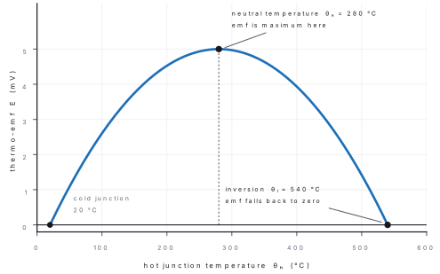
\theta_c is the cold junction, \theta_n the temperature of maximum emf, \theta_i the temperature of zero emf. The commonest error is to call \theta_i the maximum, or to forget the factor 2 in \theta_i = 2\theta_n - \theta_c. Check the arithmetic: if \theta_c = 20 °C and \theta_n = 280 °C, then \theta_i = 540 °C, not 560 °C.
Problem. A copper–constantan thermocouple has its cold junction at 30 °C and a neutral temperature of 250 °C. At what hot-junction temperature does the emf fall to zero?
Solution. \theta_i = 2\theta_n - \theta_c = 2(250) - 30 = 470 °C.
14.4.3 The Peltier effect
The Peltier effect is the reverse of Seebeck's: send a current through the junction of two dissimilar metals and the junction either absorbs or releases heat. Reverse the current and the effect reverses. The heat is proportional to the charge passed:
where \pi is the Peltier coefficient, the heat absorbed at the junction per unit charge.
| Effect | Cause | How the heat depends on current | Reversible? |
|---|---|---|---|
| Seebeck | temperature difference produces an emf | — | yes |
| Peltier | current through a junction produces or absorbs heat | \propto I | yes |
| Joule | current through a resistance produces heat | \propto I^2 | no |
| Thomson | current along a wire with a temperature gradient produces or absorbs heat | \propto I | yes |
Because Peltier heat changes sign with the current but Joule heat does not, the two can be separated experimentally.
14.4.4 The thermocouple as a thermometer, and its uses
A thermocouple thermometer has a junction so small that it measures the temperature of a point almost without disturbing it, responds quickly, works over a very wide range (from below 0 °C to over 1000 °C) and needs no power supply. Its disadvantages are a small emf (needing a sensitive galvanometer or a cold-junction compensation circuit) and the need to keep the reference junction at a known temperature.
- Thermoelectric generator — a temperature difference drives a current directly, with no moving parts; used in remote places and in radioisotope generators.
- Peltier cooler — a current cools one junction; used in small refrigerators, cooled CCD cameras and electronic component cooling.
- Industrial thermometry — thermocouples in furnaces, kilns and engines.
Formula and fact sheet
| Topic | Formula or fact |
|---|---|
| Current | I = Q/t; I = nAev_d; J = I/A = nev_d |
| Drift and mobility | v_d = eE\tau/m; \mu = e\tau/m |
| Ohm's law | V = IR at constant temperature |
| Resistance | R = \rho L/A; \rho = m/(ne^2\tau); \sigma = 1/\rho = ne^2\tau/m |
| Temperature | R_t = R_0(1+\alpha\Delta t); \alpha > 0 metals, < 0 semiconductors, \approx 0 alloys |
| Wire stretched | R \propto L^2 (volume constant); cut into n, each R/n; all parallel R/n^2 |
| emf and terminal pd | V = E - Ir; I = E/(R+r); r = R(E/V - 1) |
| Maximum power | R = r; P_{max} = E^2/4r; efficiency 50 % |
| Joule and power | H = I^2Rt; P = VI = I^2R = V^2/R |
| Units of energy | 1 kWh = 3.6\times10^6 J = 1 unit |
| Series / parallel | R_s = \Sigma R; 1/R_p = \Sigma 1/R; two: R_1R_2/(R_1+R_2) |
| Current division | I_1 = I R_2/(R_1+R_2) |
| Cells | series nE/(R+nr); parallel E/(R+r/n); mixed nE/(R+nr/m) |
| Kirchhoff | junction: \Sigma I_{in} = \Sigma I_{out}; loop: \Sigma \Delta V = 0 |
| Wheatstone | P/Q = R/S at balance |
| Metre bridge | R = S\,l/(100-l) |
| Potentiometer | E = kl; E_1/E_2 = l_1/l_2; r = R(l_1/l_2 - 1) |
| Ammeter | S = I_gG/(I-I_g); in series; ideal resistance zero |
| Voltmeter | R = V/I_g - G; in parallel; ideal resistance infinite |
| Thermocouple | \theta_i = 2\theta_n - \theta_c; \alpha = dE/dT; Peltier H = \pi It |
Chapter summary
- Current is the rate of flow of charge; I = nAev_d with a drift speed of only about 10^{-4} m s⁻¹, while the field that drives it travels at nearly light speed.
- Ohm's law V = IR holds for metals at constant temperature; R = \rho L/A, and \rho = m/(ne^2\tau) is a property of the material, unchanged by cutting or bending.
- Metals have \alpha > 0 (about 4\times10^{-3} K⁻¹), semiconductors \alpha < 0, and alloys such as manganin \alpha \approx 0, which is why they make standard resistors.
- A real cell gives V = E - Ir; the V–I graph has intercept E and slope -r, and the terminal voltage exceeds the emf only while the cell is being charged.
- P = VI = I^2R = V^2/R; use I^2R in series and V^2/R in parallel; 1 kWh = 3.6\times10^6 J, and the bill is (power in kW) × (hours) × (rate).
- Series adds resistances and shares the current; parallel adds conductances and shares the voltage. Cells in series raise the emf, in parallel lower the internal resistance, and mixed rows do both with I = nE/(R + nr/m).
- Kirchhoff: charge is conserved at a junction, energy round a loop. Fix a sign convention, solve, and check the power balance.
- Wheatstone balance P/Q = R/S; metre bridge R = Sl/(100-l), most accurate with the balance near the middle; potentiometer E \propto l, a null method that draws no current and so measures emf rather than terminal pd.
- A shunt in parallel makes an ammeter (S = I_gG/(I-I_g), ideal resistance zero); a multiplier in series makes a voltmeter (R = V/I_g - G, ideal resistance infinite).
- Seebeck: a temperature difference between two junctions of dissimilar metals gives an emf. Peltier: a current through such a junction absorbs or releases heat. The emf peaks at the neutral temperature \theta_n and vanishes at \theta_i = 2\theta_n - \theta_c.
Practice questions
Set A — Recall (28 questions)
- The drift velocity of free electrons in a metal carrying a steady current is of the order ofa10⁸ m s⁻¹b10⁻⁴ m s⁻¹c10⁶ m s⁻¹d10² m s⁻¹
- Ohm's law is obeyed whenathe conductor is heatedbthe current is alternatingcthe temperature stays constantdthe conductor is a semiconductor
- The resistivity of a conductor depends onathe material and its temperaturebits lengthcits cross-sectional areadits shape
- The SI unit of resistivity isaΩbΩ m⁻¹cΩ⁻¹ m⁻¹dΩ m
- Two resistors R_1 and R_2 joined in parallel have an equivalent resistance ofaR_1+R_2b(R_1+R_2)/2cR_1R_2/(R_1+R_2)d\sqrt{R_1R_2}
- A cell of emf E and internal resistance r delivers a current I. Its terminal potential difference isaE+IrbE-IrcE-I/rdIr
- Joule's law gives the heat produced in a resistor asaIRtbI^2Rt/2cV^2RtdI^2Rt
- One kilowatt-hour equalsa3.6\times10^6 Jb3.6\times10^3 Jc10^3 Jd3.6\times10^5 J
- Kirchhoff's junction rule is a statement of the conservation ofaenergybmomentumcchargedmass
- Kirchhoff's loop rule is based on the conservation ofachargebmomentumcmassdenergy
- The balance condition of a Wheatstone bridge isaPQ = RSbP/Q = R/ScP/R = S/QdP+Q = R+S
- In a metre bridge the unknown resistance in the left gap isaSl/(100-l)bS(100-l)/lcSl/100dS(100+l)/l
- A galvanometer is converted into an ammeter by connectingaa high resistance in seriesba low resistance in seriesca low resistance in parallelda high resistance in parallel
- A galvanometer is converted into a voltmeter by connectingaa low resistance in seriesba high resistance in seriesca low resistance in parallelda high resistance in parallel
- An ideal ammeter hasazero resistancebinfinite resistancecresistance equal to the circuitda resistance of 1 Ω
- An ideal voltmeter hasazero resistancebresistance equal to the galvanometerca small resistancedinfinite resistance
- The Seebeck effect is the production of an emf byaa current in a single metalba magnetic fieldca temperature difference between junctions of dissimilar metalsda chemical reaction
- The Peltier effect is theaabsorption or release of heat at a junction carrying currentbproduction of emf from a temperature differencecchange of resistance with temperaturedemission of electrons from a hot surface
- At the neutral temperature of a thermocoupleathe emf is zerobthe emf is maximumcthe emf reversesdthe hot junction melts
- The temperature of inversion of a thermocouple isa\theta_n+\theta_cb\theta_n-\theta_cc2\theta_n+\theta_cd2\theta_n-\theta_c
- The resistance of a metal wire rises with temperature becauseathe wire expandsbthe electrons move fastercthe relaxation time decreasesdthe number of electrons falls
- Manganin and constantan are used for standard resistors becauseatheir resistivity hardly changes with temperaturebtheir resistivity is very highcthey are cheapdthey have a large temperature coefficient
- Current density isathe total currentbcurrent per unit lengthccurrent per unit timedcurrent per unit area of cross-section
- In a series combination, the quantity that is the same through every resistor is theapotential differencebcurrentcpowerdenergy
- The potential gradient of a potentiometer wire isathe total emfbthe balance lengthcthe fall of potential per unit lengthdthe current in the wire
- The internal resistance of a cell isaE/IbV/IcE/I+Rd(E-V)/I
- A thermocouple gives its largest emf when the two metals areafar apart in the thermoelectric seriesbclose together in the seriescidenticaldboth good conductors
- The resistance of a wire of length L and area A isa\rho A/Lb\rho L/Ac\rho LAd\rho/(LA)
Answers and explanations — Set A
1. (b) — the drift speed is a fraction of a millimetre per second, about 10^{-4} m s⁻¹; 10^8 m s⁻¹ is the speed of light and of the signal, not of the electrons.
2. (c) — the law is restricted to constant temperature; heating a filament makes its I–V graph curve.
3. (a) — \rho is a material property that varies with temperature; it is independent of length, area and shape.
4. (d) — from R = \rho L/A, \rho = RA/L has units Ω m² m⁻¹ = Ω m.
5. (c) — 1/R_p = 1/R_1 + 1/R_2 gives R_p = R_1R_2/(R_1+R_2), which is smaller than either.
6. (b) — the internal resistance takes away Ir from the emf, so V = E - Ir.
7. (d) — H = I^2Rt; the V^2t/R form is equivalent but not offered here.
8. (a) — 1 kW × 3600 s = 3.6\times10^6 J.
9. (c) — charge cannot pile up at a junction, so what enters must leave.
10. (d) — the loop rule says the total work done per unit charge round a closed loop is zero.
11. (b) — at balance the galvanometer carries no current and P/Q = R/S.
12. (a) — the arms are in the ratio of their lengths, so R/S = l/(100-l).
13. (c) — a shunt in parallel carries most of the current and protects the coil.
14. (b) — a multiplier in series drops most of the voltage.
15. (a) — zero resistance means the ammeter does not alter the current it measures.
16. (d) — infinite resistance means it draws no current and so does not alter the pd.
17. (c) — the Seebeck emf needs two different metals and a temperature difference between the junctions.
18. (a) — the Peltier effect is heat absorbed or released at a junction when current passes; it reverses with the current.
19. (b) — at the neutral temperature dE/d\theta = 0, so the emf is at its peak.
20. (d) — the emf falls back to zero at \theta_i = 2\theta_n - \theta_c.
21. (c) — heating increases the lattice vibration, collisions become more frequent, \tau falls and \rho = m/(ne^2\tau) rises.
22. (a) — a very small \alpha means the resistance stays fixed as the coil warms, so the standard stays standard.
23. (d) — J = I/A, in A m⁻².
24. (b) — in series there is one path, so the current is common and the voltages add.
25. (c) — k = V/L is the potential drop per unit length along the wire.
26. (d) — from V = E - Ir, Ir = E - V, so r = (E-V)/I.
27. (a) — the wider the separation in the thermoelectric series, the larger the thermo-emf.
28. (b) — R = \rho L/A: resistance rises with length and falls with area.
Set B — Understanding (17 questions)
- A wire is stretched until its length is doubled, its volume unchanged. Its resistance becomesaR/2b2Rc4RdR
- Bulbs marked 60 W and 100 W (both 220 V) are joined in series across 220 V. Thenathe 60 W bulb glows brighterbthe 100 W bulb glows brightercboth glow equallydneither glows
- An ammeter must be connected in series becauseaits resistance is very highbits resistance is very low, so it hardly alters the currentcit measures potential differencedit stores charge
- A cell of emf E and internal resistance r feeds a resistor R. The terminal voltage is greatest whenaR = rbR < rcR = 0dR is very large compared with r
- A resistor is added in parallel to an existing combination. The total resistanceadecreasesbincreasescstays the samedbecomes zero
- In a potentiometer the balance length is proportional toathe resistance of the wirebthe current in the wirecthe emf being measureddthe total length of the wire
- A potentiometer measures emf more accurately than a voltmeter because at balanceait draws a large currentbthe cell is short-circuitedcthe galvanometer is disconnecteddno current is drawn from the cell
- The balance point of a metre bridge is taken near the middle of the wire because thereathe wire is most uniformbthe bridge is most sensitivecthe current is largestdthe resistance is zero
- A copper wire and a nichrome wire of the same length and area carry the same current in series. Thenathe copper wire gets hotterbboth get equally hotcthe nichrome wire gets hotterdneither gets hot
- The terminal voltage of a cell can exceed its emf whenathe cell is being chargedbthe cell is dischargingcthe circuit is opendthe internal resistance is zero
- Two identical cells of emf E and internal resistance r are joined in parallel across R. Compared with one cell alone, the current through Radoublesbhalvescis unchangeddincreases but does not double
- In the Peltier effect, reversing the currentadoubles the heatbreverses the effect, so heat is absorbed instead of releasedchas no effectdstops the current
- The temperature of inversion of a thermocouple depends onathe cold junction temperaturebthe metals onlycthe length of the wiresdthe current through it
- A fuse is connected in series with an appliance becauseait has a high resistancebit lowers the voltagecthe same current passes through it and it melts if that current is too largedit stores energy
- The resistance of a semiconductor falls as its temperature rises becauseaits atoms vibrate lessbits length decreasescits area increasesdthe number of charge carriers increases
- A galvanometer of resistance G is shunted by S. The resistance of the ammeter formed isaG+SbGS/(G+S)cG-SdS
- In a Wheatstone bridge, interchanging the cell and the galvanometeraleaves the balance condition unchangedbreverses the balancecdestroys the balanceddoubles the sensitivity
Answers and explanations — Set B
1. (c) — volume is constant, so doubling the length halves the area; R = \rho L/A then rises by 2\times2 = 4.
2. (a) — R = V^2/P, so the 60 W bulb has the higher resistance; in series the same current passes and P = I^2R is larger for it.
3. (b) — a very low resistance in series drops almost no voltage, so the current is practically unchanged.
4. (d) — V = E - Ir and I = E/(R+r); as R \to \infty, I \to 0 and V \to E.
5. (a) — a parallel path gives the current an extra route, so the equivalent resistance always falls.
6. (c) — E = kl with k fixed, so E \propto l; the balance length is the measure of the emf.
7. (d) — with no current through the galvanometer there is no Ir drop inside the cell, so the wire carries the full emf.
8. (b) — the fractional error in l and in (100-l) is smallest near the middle, where the bridge is most sensitive.
9. (c) — nichrome's resistivity is about sixty times copper's, so I^2R is far larger in it.
10. (a) — when a stronger source drives current into the cell, V = E + Ir, which is greater than E.
11. (d) — E/(R+r/2) is larger than E/(R+r) but less than twice it, because the emf is unchanged.
12. (b) — Peltier heat changes sign with the current; that reversibility is what distinguishes it from Joule heating.
13. (a) — \theta_i = 2\theta_n - \theta_c, and \theta_n is fixed by the pair of metals, so \theta_i moves with the cold junction.
14. (c) — the fuse is in series so that the whole appliance current passes through it; it melts above its rating.
15. (d) — heating breaks bonds and frees many more carriers, and the rise in n outweighs the fall in \tau.
16. (b) — the shunt is in parallel with the coil, so R_A = GS/(G+S), smaller than either.
17. (a) — the balance condition P/Q = R/S does not depend on which diagonal holds the cell.
Set C — Application (11 questions)
- A current of 1.0 A flows in a copper wire of cross-section 1 mm². Taking n = 8.5\times10^{28} m⁻³, the drift velocity is abouta7.4\times10^{-2} m s⁻¹b7.4\times10^{-5} m s⁻¹c7.4\times10^{-8} m s⁻¹d7.4\times10^{3} m s⁻¹
- A copper wire of resistivity 1.7\times10^{-8} Ω m has length 2 m and cross-section 1 mm². Its resistance isa3.4\times10^{-4} Ωb3.4 Ωc0.34 Ωd3.4\times10^{-2} Ω
- A coil has resistance 5 Ω at 20 °C and a temperature coefficient 4\times10^{-3} °C⁻¹. Its resistance at 120 °C isa7 Ωb5.2 Ωc9 Ωd25 Ω
- A 1500 W heater runs 4 hours a day for 30 days. At Rs 11 per unit, the cost isaRs 198bRs 660cRs 1980dRs 3300
- Four cells, each of emf 1.5 V and internal resistance 0.5 Ω, are joined in series across a 4 Ω resistor. The current isa1.5 Ab1 Ac0.75 Ad0.375 A
- Eight cells, each of emf 1.5 V and internal resistance 0.5 Ω, are arranged in 2 rows of 4 and connected to a 1 Ω resistor. The current isa3 Ab1.5 Ac6 Ad0.75 A
- In a metre bridge a 6 Ω resistor in the right gap balances at 40 cm from the left end. The resistance in the left gap isa9 Ωb2.4 Ωc15 Ωd4 Ω
- A potentiometer wire 10 m long has a steady 2 V across it. A cell balances at 3.5 m. Its emf isa0.35 Vb2.0 Vc0.7 Vd1.4 V
- A galvanometer of resistance 50 Ω gives full-scale deflection at 1 mA. The shunt needed to make it an ammeter of range 1 A is abouta50 Ωb0.05 Ωc0.5 Ωd5 Ω
- The same galvanometer (50 Ω, 1 mA) is to become a voltmeter of range 10 V. The series resistance needed isa50 Ωb5000 Ωc9950 Ωd10000 Ω
- A thermocouple has its cold junction at 20 °C and a neutral temperature of 280 °C. Its temperature of inversion isa540 °Cb300 °Cc560 °Cd140 °C
Answers and explanations — Set C
1. (b) — v_d = I/(nAe) = 1/(8.5\times10^{28}\times10^{-6}\times1.6\times10^{-19}) \approx 7.4\times10^{-5} m s⁻¹.
2. (d) — R = \rho L/A = (1.7\times10^{-8})(2)/(10^{-6}) = 3.4\times10^{-2} Ω.
3. (a) — R = 5[1 + 4\times10^{-3}(100)] = 5(1.4) = 7 Ω.
4. (c) — energy = 1.5\times4\times30 = 180 kWh; cost = 180\times11 = Rs 1980.
5. (b) — I = 4(1.5)/(4 + 4\times0.5) = 6/6 = 1 A. Option (a) forgets the internal resistance.
6. (a) — I = nE/(R + nr/m) = 6/(1 + 1) = 3 A with n = 4, m = 2.
7. (d) — R = Sl/(100-l) = 6(40)/60 = 4 Ω. Option (a) inverts the ratio.
8. (c) — k = 2/10 = 0.2 V m⁻¹, so E = kl = 0.2\times3.5 = 0.7 V.
9. (b) — S = I_gG/(I-I_g) = (10^{-3})(50)/(0.999) \approx 0.05 Ω.
10. (c) — R = V/I_g - G = 10/10^{-3} - 50 = 9950 Ω; 10000 Ω forgets to subtract the coil resistance.
11. (a) — \theta_i = 2\theta_n - \theta_c = 560 - 20 = 540 °C.