Chapter 16 · Current Electricity and Magnetism · 3 questions in the paper · 34 min read
Electromagnetic Induction and Alternating Current
What the syllabus asks for 4
- Faraday's and Lenz's laws; the AC generator, the transformer and eddy currents
- Self and mutual inductance; energy stored in an inductor
- Peak and rms values; impedance, phase, power and Q-factor of LCR circuits
- Rectification with a diode bridge
This chapter is where a changing magnetic field becomes a voltage. The area Current Electricity and Magnetism carries 9 of the 50 Physics questions (official MEC weightage), and we estimate 3 come from here. The paper asks for Faraday's law in one-line form, the direction of an induced current, the peak emf of a generator, a transformer ratio, the rms value, an impedance or resonance calculation, and the shape of a rectified waveform. The marks are lost on three things: rms against peak in a power calculation, a transformer claimed to work on DC, and the direction of Lenz's law.
- \Phi=BA\cos\theta; \varepsilon=-N\,d\Phi/dt; average emf N\Delta\Phi/\Delta t; motional emf \varepsilon=Bvl.
- Lenz's law: the induced current opposes the change that produced it — energy conservation, not a arbitrary rule about poles.
- The force needed to keep a rod moving, F=B^2l^2v/R, and the power Fv=\varepsilon^2/R.
- Generator: \varepsilon=NBA\omega\sin\omega t, peak \varepsilon_0=NBA\omega; the transformer: V_s/V_p=N_s/N_p=I_p/I_s, AC only, no change of frequency; eddy currents and lamination.
- Self and mutual inductance, \varepsilon=-L\,dI/dt, L=\mu_0N^2A/l, U=\frac12LI^2.
- rms =I_0/\sqrt{2}; X_L=\omega L, X_C=1/\omega C; Z=\sqrt{R^2+(X_L-X_C)^2}; resonance at f_0=1/(2\pi\sqrt{LC}); P=V_{rms}I_{rms}\cos\phi; Q=\omega_0L/R.
- The bridge rectifier: four diodes, both half-cycles, ripple frequency 2f.
16.1 Faraday's and Lenz's laws; the AC generator, the transformer and eddy currents
16.1.1 Magnetic flux and flux linkage
The magnetic flux through a surface is the number of field lines crossing it:
where A is the area, B the flux density and \theta the angle between \vec B and the normal to the surface. The unit is the weber (Wb): 1 Wb = 1 T m².
For a coil of N turns, each turn encloses the same flux, so the flux linkage is N\Phi. It is measured in weber-turns, numerically equal to Wb.
| Situation | \theta | Flux |
|---|---|---|
| Surface perpendicular to \vec B | 0° | maximum, BA |
| Surface parallel to \vec B | 90° | zero |
| Coil rotated from perpendicular to parallel | 0° → 90° | falls from BA to 0 |
16.1.2 Faraday's law
The emf induced in a circuit equals the negative rate of change of magnetic flux linkage through it:
The average emf over a time interval is
The emf can be raised by more turns, a stronger field, a larger area, or a faster change. It is the rate of change that matters, not the flux itself: a coil sitting in a strong steady field has no induced emf at all.
The minus sign is Lenz's law, and it is not optional bookkeeping — it is the statement that the induced emf drives a current whose own field opposes the change.
16.1.3 Lenz's law and energy conservation
The direction of the induced current is such that it opposes the change in flux that produced it.
Push the north pole of a bar magnet towards a coil. The flux through the coil increases towards the magnet, so the induced current makes the near face of the coil a north pole, which repels the approaching magnet. Pull the magnet away and the flux decreases, so the near face becomes a south pole and attracts it. Either way the coil fights the motion.
That fight is where the energy comes from. You do mechanical work against the repulsion; the induced current dissipates that work as heat in the coil's resistance. If the induced current instead helped the magnet, the magnet would accelerate for free and the circuit would deliver energy from nothing. Lenz's law is therefore the law of conservation of energy in disguise.
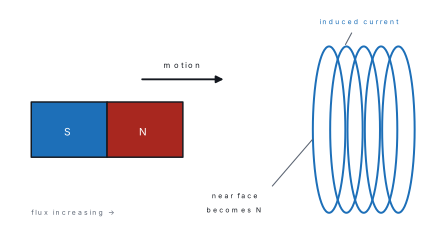
| Change in flux | Induced current | Result |
|---|---|---|
| Flux into the coil increases | Sets up a field out of the coil | Opposes the increase |
| Flux into the coil decreases | Sets up a field into the coil | Opposes the decrease |
| Magnet approaches, N pole first | Near face becomes N | Repels the magnet |
| Magnet recedes, N pole first | Near face becomes S | Attracts the magnet |
The induced current does not oppose the flux; it opposes the change in flux. A coil in a strong steady field has no induced current at all, and a coil in a weak field that is changing fast has a large one. Questions that say "the flux is large, so the induced emf is large" are testing exactly this confusion.
16.1.4 Motional emf
A conducting rod of length l moves with speed v perpendicular to a uniform field B, on rails that form a closed circuit. The free electrons in the rod move with it and feel a magnetic force qvB along the rod; charge separates until the electric field along the rod balances it, giving an emf
The same result comes from Faraday's law. In time dt the rod sweeps area lv\,dt, so the flux changes by Blv\,dt and \varepsilon=d\Phi/dt=Blv.
If the circuit has resistance R,
The force is the magnetic drag on the rod, and it points opposite to the motion. To keep the rod moving at constant speed you must pull with this force, delivering mechanical power
which is exactly the electrical power I^2R dissipated in the circuit. The mechanical work you do becomes heat — Lenz's law again, now in numbers.
Two powers, one answer
F=B^2l^2v/R grows as v^2 in the power, so doubling the speed of the rod needs four times the force? No — the force itself goes as v, and the power as v^2. Read the question: it may ask for the force, the power, or the current.
Problem. A rod 0.50 m long moves at 4.0 m s⁻¹ perpendicular to a field of 0.20 T. The circuit resistance is 0.20 Ω. Find the emf, the current, the force needed to keep the rod moving, and the power dissipated.
Solution. \varepsilon=Bvl=(0.20)(4.0)(0.50)=0.40\ \text{V}.
I=\varepsilon/R=0.40/0.20=2.0\ \text{A}.
F=BIl=(0.20)(2.0)(0.50)=0.20\ \text{N}.
P=Fv=(0.20)(4.0)=0.80\ \text{W}, and I^2R=(2.0)^2(0.20)=0.80\ \text{W} ✓.
16.1.5 The AC generator
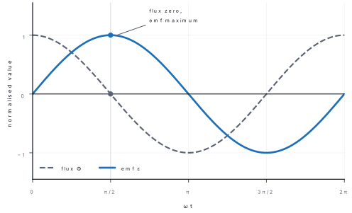
A rectangular coil of N turns and area A rotates with constant angular speed \omega in a uniform field B. The flux through it is
so the induced emf is
| Position of the coil | Flux | Rate of change | emf |
|---|---|---|---|
| Plane perpendicular to \vec B | maximum, NBA | zero | zero |
| Plane parallel to \vec B | zero | maximum | maximum, \varepsilon_0 |
| After a quarter turn from perpendicular | zero | maximum | maximum |
The emf is not maximum when the flux is maximum; it is maximum when the flux is changing fastest, which is when the flux is zero. The two are a quarter cycle apart.
The coil ends are joined to two slip rings with brushes, so the output is alternating. A split-ring commutator instead reverses the connections every half turn and gives direct current — that is the difference between an AC and a DC generator.
Problem. A coil of 200 turns and area 0.020 m² rotates at 60 rad s⁻¹ in a field of 0.50 T. Find the peak emf and the emf when the plane of the coil is at 30° to the field.
Solution. \varepsilon_0=NBA\omega=(200)(0.50)(0.020)(60)=120\ \text{V}.
When the plane is at 30° to the field, the normal is at 60^{\circ} to it, so \omega t=60^{\circ} from the perpendicular position and \varepsilon=\varepsilon_0\sin60^{\circ}=120(0.866)=104\ \text{V}.
Watch the angle: \sin\omega t is measured from the position of maximum flux, where the plane is perpendicular to the field.
16.1.6 The transformer
A transformer has two coils wound on a common laminated soft-iron core. Alternating current in the primary sets up an alternating flux in the core; that flux links the secondary and induces an emf in it. Because the same flux passes through each turn of both coils, the emf per turn is the same:
For an ideal transformer (no losses) the power in equals the power out, V_pI_p=V_sI_s, so
A step-up transformer has N_s>N_p: it raises the voltage and lowers the current. A step-down transformer has N_s<N_p: it lowers the voltage and raises the current.
| Step-up | Step-down | |
|---|---|---|
| Turns | N_s>N_p | N_s<N_p |
| Voltage | rises | falls |
| Current | falls | rises |
| Power (ideal) | unchanged | unchanged |
| Example | transmission line at 132 kV | 220 V supply to a 12 V charger |
Why it needs AC. The secondary emf depends on d\Phi/dt. A direct current gives a steady flux, d\Phi/dt=0, and no secondary emf at all — the transformer simply does not work on DC, and connecting one to a DC supply can burn out the primary because there is no back emf to limit the current. For the same reason a transformer cannot change the frequency: one cycle of the primary flux produces exactly one cycle of secondary emf.
Losses and remedies.
| Loss | Cause | Remedy |
|---|---|---|
| Copper loss | I^2R heating in the windings | thick wire of low resistivity |
| Eddy-current loss | currents induced in the solid core | laminated core, thin insulated sheets |
| Hysteresis loss | repeated magnetisation of the core | soft iron core with a narrow loop |
| Flux leakage | flux that misses the secondary | wind the coils close together on the same core |
Efficiency \eta=P_{out}/P_{in}\times100\,\%; a good large transformer reaches 98 %.
A transformer does not change the frequency, does not work on steady DC, and does not create power. It changes voltage and current in opposite directions, and the product VI stays (almost) the same. "A step-up transformer increases the power" is wrong in three separate ways.
Problem. A transformer has 1000 primary turns and 50 secondary turns. The primary is connected to 220 V and delivers 2.0 A. Find the secondary voltage and current, assuming an ideal transformer.
Solution. \dfrac{V_s}{V_p}=\dfrac{N_s}{N_p}=\dfrac{50}{1000}=0.05, so V_s=0.05(220)=11\ \text{V}.
V_pI_p=220(2.0)=440\ \text{W}, so I_s=440/11=40\ \text{A}.
The voltage falls by 20 and the current rises by 20 — the power is unchanged.
16.1.7 Eddy currents
When a bulk piece of metal sits in a changing magnetic field (or moves through a non-uniform one), emfs are induced throughout its volume and circulate in closed loops. These are eddy currents. By Lenz's law they oppose the change that causes them, so they produce a dragging force on a moving conductor and heat in a stationary one.
| Effect of eddy currents | Application |
|---|---|
| Retarding force on a conductor moving in a field | electromagnetic braking of trains and balances |
| Heating of the metal | induction furnace, induction cooker |
| Opposing rotation | damping of galvanometer coils, speedometer |
| Energy loss in a core | the problem that lamination solves |
Lamination cuts the conducting path into thin sheets separated by insulation, so the eddy loops can only be small and the loss falls sharply. Eddy-current loss grows as B^2f^2t^2 for sheet thickness t, which is why cores are made of thin sheets and why high-frequency cores use ferrite.
16.2 Self and mutual inductance; energy stored in an inductor
16.2.1 Self-inductance
A current in a coil produces flux through the coil itself. If the current changes, that flux changes and induces an emf in the same coil — self-induction. For a coil of N turns,
L is the self-inductance, measured in henry (H): 1 H = 1 Wb A⁻¹ = 1 V s A⁻¹. It depends only on the geometry of the coil and on the core material, not on the current.
For a long solenoid of N turns, area A, length l (with n=N/l),
The N^2 is worth remembering: doubling the number of turns on the same former quadruples the inductance.
The back emf. When you close a switch on a coil, the current rises gradually, because the growing current induces an emf that opposes the growth. When you open the switch, the current tries to fall quickly, the induced emf is large and in the direction that maintains the current — which is why a switch on an inductive circuit sparks, and why a fluorescent lamp needs a choke. An inductor is the electrical analogue of mass: it resists any change in its current.
| Element | Resists change of | Law |
|---|---|---|
| Resistor | current (by dissipating energy) | V=IR |
| Capacitor | voltage | Q=CV |
| Inductor | current | \varepsilon=-L\,dI/dt |
16.2.2 Mutual inductance
Two coils close together are coupled: a changing current in coil 1 changes the flux through coil 2 and induces an emf there. For a flux linkage N_2\Phi_2 in the secondary,
M is the mutual inductance, also in henry. It depends on the geometry of both coils, their separation and orientation, and the core between them — but not on the current. For two coils of N_1 and N_2 turns wound on the same long solenoid of area A and length l,
The reciprocity theorem states M_{12}=M_{21}: the emf in coil 2 per unit rate of change of current in coil 1 equals the emf in coil 1 for the same rate of change in coil 2. The transformer is the standard application.
L and M do not change when the current changes. What changes is the emf, which is proportional to dI/dt. A question that says "the current is doubled, so the inductance doubles" is wrong; doubling the current only doubles the stored energy and the flux.
16.2.3 Energy stored in an inductor
Building up a current in an inductor requires work against the back emf. The work done in raising the current from 0 to I is
Setting up. A coil of inductance L carries a current i that is rising. The back emf is \varepsilon=L\,di/dt (magnitude), so the source must supply power P=\varepsilon i.
Step 1 — power delivered against the back emf.
Step 2 — power is the rate of change of stored energy.
Step 3 — integrate from i=0 to i=I.
Result. U=\frac12LI^2 joules.
What it means. The energy is stored in the magnetic field, not in the wire. For a long solenoid, dividing U by the volume Al and using B=\mu_0nI gives the energy density
so every cubic metre of a 1 T field holds about 4\times10^{5} J.
Problem. A solenoid 0.40 m long has 800 turns of area 5.0\times10^{-4} m². Find its self-inductance and the energy stored when it carries 3.0 A.
Solution. L=\dfrac{\mu_0N^2A}{l}=\dfrac{(4\pi\times10^{-7})(800)^2(5.0\times10^{-4})}{0.40} =1.0\times10^{-3}\ \text{H}.
U=\frac12LI^2=\frac12(1.0\times10^{-3})(3.0)^2=4.5\times10^{-3}\ \text{J}.
The inductance is about a millihenry — typical of a laboratory coil, and a reminder that 1 H is a large unit.
16.3 Peak and rms values; impedance, phase, power and Q-factor of LCR circuits
16.3.1 Peak, mean and rms values
An alternating current reverses direction periodically. Write it as
| Value | Symbol | Expression | For i_0=1 A |
|---|---|---|---|
| Peak (maximum) | i_0 | — | 1.000 A |
| Mean over a full cycle | \bar i | 0 | 0 |
| Mean over a half cycle | \bar i | 2i_0/\pi | 0.637 A |
| Root mean square | i_{rms} | i_0/\sqrt{2} | 0.707 A |
The full-cycle mean is zero because the positive and negative halves cancel, so a moving-coil meter (which responds to the mean) reads zero on AC. The rms value is the value of the direct current that would produce the same heating in a resistor, and it is what AC meters and the 220 V mains rating mean.
The form factor is I_{rms}/\bar I=0.707/0.637=1.11 for a sine wave.
The power is P=V_{rms}I_{rms}\cos\phi, not V_0I_0\cos\phi. Using peak values gives an answer twice too large. Equivalently P=\frac12V_0I_0\cos\phi — the factor \frac12 and the two 1/\sqrt{2} factors are the same statement.
16.3.2 Resistance, reactance and impedance
| Circuit element | Opposition | Symbol | Phase of current relative to voltage |
|---|---|---|---|
| Resistor R | resistance R | R | in phase |
| Inductor L | inductive reactance | X_L=\omega L | lags by 90° |
| Capacitor C | capacitive reactance | X_C=1/\omega C | leads by 90° |
X_L rises with frequency (a rapid change is harder to establish in a coil); X_C falls with frequency (a capacitor passes rapid changes more easily). At very high frequency an inductor is nearly an open circuit and a capacitor nearly a short circuit.
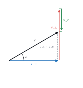
Series LCR circuit. The same current flows through all three, so the voltages are V_R=IR, V_L=IX_L, V_C=IX_C. The voltages across L and C are 180° out of phase and partly cancel. Adding them as phasors gives the supply voltage
so the impedance is
where \phi is the phase angle by which the voltage leads the current. If X_L>X_C, \phi>0 and the circuit is inductive (current lags). If X_C>X_L, the circuit is capacitive (current leads).
Problem. A series circuit has R=30\ \Omega, X_L=70\ \Omega and X_C=30\ \Omega, connected to a 200 V (rms) supply. Find Z, the current and the phase angle.
Solution. X_L-X_C=40\ \Omega, so Z=\sqrt{30^2+40^2}=50\ \Omega.
I_{rms}=V_{rms}/Z=200/50=4.0\ \text{A}.
\tan\phi=40/30=1.33, so \phi=53^{\circ} with the voltage leading — an inductive circuit, current lagging.
16.3.3 Resonance
As the frequency of the supply is varied, X_L rises and X_C falls. At one frequency they are equal and cancel exactly:
At resonance:
- Z=R, the minimum possible impedance;
- I=V/R, the maximum current;
- \phi=0, so the current and voltage are in phase and the power factor is 1;
- V_L and V_C are equal in magnitude and opposite in phase, so they cancel in the supply voltage — but each can be much larger than the supply voltage.
That last point is the useful and dangerous one. Since V_L=IX_L and I=V/R,
the quality factor. A circuit with Q=100 develops 100 times the supply voltage across the capacitor — the principle of radio tuning, and the reason a resonant circuit can destroy itself.
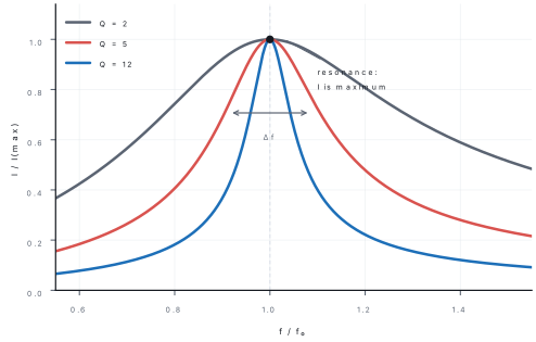
where \Delta f is the bandwidth, the width of the resonance curve at I=I_{max}/\sqrt{2}. A high Q means a tall, narrow peak: the circuit responds strongly to one frequency and hardly at all to its neighbours.
| At resonance | Value |
|---|---|
| Impedance | Z=R (minimum) |
| Current | I=V/R (maximum) |
| Phase angle | 0 |
| Power factor | 1 |
| V_L and V_C | equal, opposite, each Q times the supply |
| Frequency | f_0=1/(2\pi\sqrt{LC}) |
At resonance the total reactance is zero, so the impedance is smallest and the current largest. Distractors offer "impedance maximum" or "current zero". Also, the voltage across the capacitor is not zero — it is Q times the supply voltage.
Problem. A series LCR circuit has L=1.0 mH, C=1.0\ \muF and R=10\ \Omega. Find the resonant frequency, the Q-factor and the bandwidth.
Solution. f_0=\dfrac{1}{2\pi\sqrt{LC}} =\dfrac{1}{2\pi\sqrt{(1.0\times10^{-3})(1.0\times10^{-6})}} =\dfrac{1}{2\pi(3.16\times10^{-5})}=5.0\times10^{3}\ \text{Hz}.
Q=\dfrac{1}{R}\sqrt{\dfrac{L}{C}}=\dfrac{1}{10}\sqrt{\dfrac{10^{-3}}{10^{-6}}} =\dfrac{1}{10}(31.6)=3.2.
\Delta f=f_0/Q=5000/3.2=1.6\times10^{3}\ \text{Hz} — a broad, low-Q resonance.
16.3.4 Power in an AC circuit
The instantaneous power p=vi rises and falls, and can even be negative for part of the cycle (energy returned to the supply by a capacitor or inductor). The average power over a cycle is
where \cos\phi=R/Z is the power factor.
| Circuit | \phi | \cos\phi | Average power |
|---|---|---|---|
| Pure R | 0 | 1 | V_{rms}I_{rms} |
| Pure L | 90° | 0 | 0 |
| Pure C | 90° | 0 | 0 |
| Series LCR | between | R/Z | I_{rms}^2R |
In a purely reactive circuit the current is wattless: it flows, the ammeter reads it, but no net energy is consumed — the energy shuttles back and forth between the source and the field. The wattless component of a general current is I_{rms}\sin\phi, and the active (power-carrying) component is I_{rms}\cos\phi.
Note also that P=I_{rms}^2R always, whatever the reactances: only the resistance dissipates energy.
Problem. An AC circuit draws 2.0 A (rms) at 220 V (rms) with a phase angle of 60°. Find the power, the power factor and the wattless current.
Solution. P=V_{rms}I_{rms}\cos\phi=(220)(2.0)(0.50)=220\ \text{W}.
Power factor \cos60^{\circ}=0.50.
Wattless current =I_{rms}\sin60^{\circ}=2.0(0.866)=1.7\ \text{A}.
The other 1.0 A is the active component, and 220\times1.0=220 W ✓.
16.4 Rectification with a diode bridge
16.4.1 The diode as a one-way valve
A p–n junction diode conducts when it is forward biased (p side positive) and blocks when it is reverse biased. In the forward direction a small voltage (about 0.7 V for silicon) is needed before the current rises steeply; in reverse only a tiny leakage current flows until breakdown. Rectification is the conversion of AC into a unidirectional (pulsating DC) current using this one-way property.
16.4.2 Half-wave rectification
One diode in series with the load passes current only during the half cycle in which it is forward biased. The output is a series of pulses with gaps:
| Quantity | Half-wave |
|---|---|
| Diodes | 1 |
| Output pulses per input cycle | 1 |
| Ripple frequency | f (50 Hz for 50 Hz mains) |
| Mean (DC) output | V_0/\pi=0.318V_0 |
| rms output | V_0/2 |
| Ripple factor | 1.21 |
| Efficiency | about 40.6 % |
16.4.3 The full-wave bridge rectifier
Four diodes in a bridge pass current through the load in the same direction on both half cycles. On the positive half, diodes D1 and D3 conduct; on the negative half, D2 and D4 conduct. The load therefore sees a pulse for every half cycle.
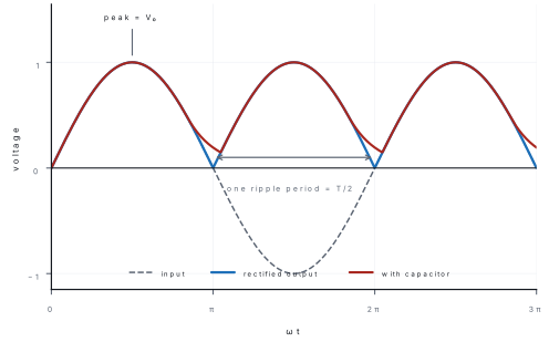
| Quantity | Half-wave | Full-wave bridge |
|---|---|---|
| Diodes | 1 | 4 |
| Pulses per cycle | 1 | 2 |
| Ripple frequency | f | 2f |
| Mean output | 0.318V_0 | 0.637V_0 |
| rms output | 0.500V_0 | 0.707V_0 |
| Ripple factor | 1.21 | 0.48 |
| Efficiency | 40.6 % | 81.2 % |
| Peak inverse voltage per diode | V_0 | V_0 |
The bridge is better on every count except that it uses four diodes and two of them are always in series with the load, so the output is lower than the peak by about 1.4 V.
Smoothing. A large capacitor across the load charges to the peak and discharges slowly through the load between peaks, filling the gaps. The residual variation is the ripple, and it falls as C and as the load resistance rise. A regulator stage after the capacitor gives a steady DC.
A rectifier produces pulsating DC, not a steady battery voltage, and it does not change the power available. The output frequency of the ripple is twice the input frequency for a full-wave rectifier — a very common question. And a diode is not a resistor: its forward resistance is small but not zero, and it drops about 0.7 V.
Problem. A bridge rectifier is fed with 50 Hz AC whose peak voltage is 12 V. Find the ripple frequency and the mean output voltage (ignore the diode drops).
Solution. Ripple frequency =2f=100\ \text{Hz}.
Mean output =\dfrac{2V_0}{\pi}=\dfrac{2(12)}{\pi}=7.6\ \text{V}.
The rms output would be V_0/\sqrt{2}=8.5 V; the mean is lower because the waveform is not sinusoidal.
Formula and fact sheet
| Topic | Formula or fact |
|---|---|
| Flux | \Phi=BA\cos\theta; unit weber, 1 Wb = 1 T m² |
| Faraday's law | \varepsilon=-N\,d\Phi/dt; average \bar\varepsilon=-N\Delta\Phi/\Delta t |
| Lenz's law | induced current opposes the change in flux; energy conservation |
| Motional emf | \varepsilon=Bvl; I=Bvl/R; F=B^2l^2v/R; P=Fv=\varepsilon^2/R |
| Generator | \varepsilon=NBA\omega\sin\omega t; \varepsilon_0=NBA\omega; slip rings for AC |
| Transformer | V_s/V_p=N_s/N_p=I_p/I_s; AC only; frequency unchanged |
| Transformer losses | copper (I^2R), eddy (laminate), hysteresis (soft iron), leakage |
| Eddy currents | oppose motion, heat metal; reduced by lamination |
| Self-inductance | N\Phi=LI; \varepsilon=-L\,dI/dt; 1 H = 1 V s A⁻¹ |
| Solenoid | L=\mu_0N^2A/l=\mu_0n^2Al |
| Mutual inductance | N_2\Phi_2=MI_1; \varepsilon_2=-M\,dI_1/dt; M=\mu_0N_1N_2A/l; M_{12}=M_{21} |
| Inductor energy | U=\frac12LI^2; energy density B^2/2\mu_0 |
| AC values | I_{rms}=i_0/\sqrt{2}=0.707i_0; half-cycle mean 2i_0/\pi=0.637i_0; full-cycle mean 0 |
| Reactance | X_L=\omega L (current lags 90°); X_C=1/\omega C (current leads 90°) |
| Series LCR | Z=\sqrt{R^2+(X_L-X_C)^2}; \tan\phi=(X_L-X_C)/R |
| Resonance | f_0=1/(2\pi\sqrt{LC}); Z=R; I maximum; \phi=0 |
| Q-factor | Q=\omega_0L/R=1/\omega_0CR=(1/R)\sqrt{L/C}=f_0/\Delta f |
| Power | P=V_{rms}I_{rms}\cos\phi=I_{rms}^2R; wattless current I_{rms}\sin\phi |
| Rectifier | half: 0.318V_0, ripple f, factor 1.21; bridge: 0.637V_0, ripple 2f, factor 0.48 |
Chapter summary
- The flux through a coil is \Phi=BA\cos\theta; the emf is the negative rate of change of flux linkage, \varepsilon=-N\,d\Phi/dt, and only a changing flux induces one.
- Lenz's law says the induced current opposes the change in flux; that opposition is what makes the law a statement of energy conservation.
- A rod moving across a field has \varepsilon=Bvl; the magnetic drag is B^2l^2v/R and the mechanical power you supply equals the I^2R heat produced.
- A coil rotating in a field gives \varepsilon=NBA\omega\sin\omega t; the peak emf is NBA\omega and it occurs when the flux through the coil is zero.
- A transformer obeys V_s/V_p=N_s/N_p=I_p/I_s; it needs alternating current, cannot change the frequency, and loses energy to copper, eddy currents, hysteresis and leakage.
- Self-inductance is N\Phi=LI with \varepsilon=-L\,dI/dt; a solenoid has L=\mu_0N^2A/l, and the stored energy is \frac12LI^2, in the field with density B^2/2\mu_0.
- Mutual inductance M couples two coils and is the basis of the transformer; M_{12}=M_{21}.
- rms values are peak values divided by \sqrt{2}; the power is V_{rms}I_{rms}\cos\phi, never V_0I_0\cos\phi.
- In series LCR, Z=\sqrt{R^2+(X_L-X_C)^2}; at resonance X_L=X_C, Z=R, the current is maximum and the voltages across L and C are Q times the supply.
- A bridge rectifier uses four diodes, conducts on both half cycles, gives a mean output 2V_0/\pi and a ripple at twice the supply frequency.
Practice questions
Set A — Recall (28 questions)
- The SI unit of magnetic flux isateslabhenrycweberdfarad
- Faraday's law of induction is written asaN\,d\Phi/dtb-N\,d\Phi/dtc-N\Phi/t^2d-d\Phi/dx
- Lenz's law is a consequence of the conservation ofachargebmomentumcmassdenergy
- The emf induced in a rod of length l moving with speed v perpendicular to B isaBvlbBv/lcBvl^2dBv^2l
- The peak emf of a generator of N turns, area A, rotating with angular speed ω isaNBA/\omegabNB\omega/AcNBA\omegadNAB^2\omega
- In a transformer the ratio of secondary to primary voltage equalsaN_p/N_sbN_s/N_pcI_s/I_pdN_s^2/N_p^2
- A transformer works onaalternating current onlybdirect current onlycboth AC and DCdneither
- Eddy currents in a transformer core are reduced byausing a solid corebincreasing the frequencycusing thick wiredlaminating the core
- The SI unit of self-inductance isaweberbhenryctesladfarad
- The energy stored in an inductor of inductance L carrying current I isaLIbLI^2c\frac12LI^2d\frac12L^2I
- The self-inductance of a solenoid of N turns, area A and length l isa\mu_0N^2A/lb\mu_0NA/lc\mu_0N^2A/l^2d\mu_0N^2l/A
- The rms value of an alternating current of peak value i_0 isa2i_0/\pibi_0/2ci_0di_0/\sqrt{2}
- In a purely inductive circuit the currentaleads the voltage by 90°blags the voltage by 90°cis in phasedleads by 45°
- In a purely capacitive circuit the currentaleads the voltage by 90°blags the voltage by 90°cis in phasedlags by 45°
- The reactance of an inductor of inductance L at angular frequency ω isa\omega/Lb1/\omega Lc\omega Ld1/\omega^2L
- The reactance of a capacitor C at angular frequency ω isa\omega Cb\omega/Cc1/\omega^2Cd1/\omega C
- At resonance in a series LCR circuitathe impedance is maximumbthe impedance equals R and the current is maximumcthe current is zerodthe power factor is zero
- The resonant frequency of a series LCR circuit isa1/(2\pi\sqrt{LC})b2\pi\sqrt{LC}c1/(2\pi LC)d\sqrt{LC}/(2\pi)
- The average power in an AC circuit isaV_{rms}I_{rms}bV_{rms}I_{rms}\sin\phicV_{rms}I_{rms}\cos\phidV_0I_0\cos\phi
- The power factor of a purely resistive circuit isazerob0.5c0.707d1
- A full-wave bridge rectifier usesaone diodebfour diodesctwo diodesdthree diodes
- The ripple frequency of a bridge rectifier fed with 50 Hz AC isa25 Hzb50 Hzc100 Hzd200 Hz
- A step-down transformer is one in whichathe secondary has fewer turns than the primarybthe secondary has more turns than the primarycthe two have equal turnsdthere is no core
- The Q-factor of a series LCR circuit isaR/\omega_0Lb\omega_0CRcR\sqrt{C/L}d(1/R)\sqrt{L/C}
- The mutual inductance between two coils depends onathe current in the primary onlybthe geometry and relative position of the coilscthe resistance of the coilsdthe frequency of the current
- The direction of the induced current in a coil is given byaFleming's left-hand rulebAmpère's circuital lawcLenz's lawdCoulomb's law
- The mean value of an alternating current over a complete cycle isazerobi_0/\sqrt{2}c2i_0/\pidi_0
- An ideal inductor in a steady DC circuit behaves asaan open circuitba short circuitca capacitorda battery
Answers and explanations — Set A
1. (c) — the weber is 1 T m². Tesla is flux density, henry is inductance.
2. (b) — the minus sign is Lenz's law; dropping it gives only the magnitude.
3. (d) — if the induced current aided the change, energy would be created; the opposition is energy conservation.
4. (a) — the rod sweeps area lv\,dt in time dt, so d\Phi/dt=Blv.
5. (c) — \varepsilon=NBA\omega\sin\omega t, so the peak is NBA\omega.
6. (b) — the emf per turn is the same in both coils, so V_s/V_p=N_s/N_p.
7. (a) — a steady DC gives a steady flux, d\Phi/dt=0, and no secondary emf.
8. (d) — thin insulated sheets break up the eddy-current loops.
9. (b) — 1 H = 1 V s A⁻¹.
10. (c) — U=\frac12LI^2, the electrical analogue of \frac12mv^2.
11. (a) — L=\mu_0N^2A/l; the N^2 comes from the flux per turn being proportional to N as well.
12. (d) — i_{rms}=i_0/\sqrt{2}; 2i_0/\pi is the half-cycle mean.
13. (b) — in an inductor the voltage leads the current by 90°, so the current lags.
14. (a) — in a capacitor the current leads the voltage by 90° (the mnemonic ICE).
15. (c) — X_L=\omega L, rising with frequency.
16. (d) — X_C=1/\omega C, falling with frequency.
17. (b) — X_L and X_C cancel, leaving Z=R: the smallest impedance and the largest current.
18. (a) — \omega_0=1/\sqrt{LC}, so f_0=1/(2\pi\sqrt{LC}).
19. (c) — only the component of current in phase with the voltage carries power.
20. (d) — \phi=0, so \cos\phi=1.
21. (b) — four diodes, two conducting on each half cycle.
22. (c) — two pulses per input cycle, so 2\times50=100 Hz.
23. (a) — fewer secondary turns means a lower secondary voltage.
24. (d) — Q=(1/R)\sqrt{L/C}, also equal to \omega_0L/R.
25. (b) — M is fixed by geometry, separation, orientation and the core; it does not depend on the current.
26. (c) — Lenz's law gives the direction; Fleming's left-hand rule is for the force on a current.
27. (a) — the positive and negative halves cancel, which is why a moving-coil meter reads zero on AC.
28. (b) — with a steady current dI/dt=0, so there is no back emf and an ideal coil has zero resistance.
Set B — Understanding (17 questions)
- A bar magnet is pushed into a coil with its north pole first. The face of the coil nearer the magnetabecomes a south pole and attracts the magnetbbecomes a north pole and repels the magnetcstays unmagnetiseddalternates in polarity
- A copper ring is dropped over a vertical bar magnet. Its acceleration isagreater than gbequal to gczerodless than g
- The induced emf in a coil is doubled ifathe number of turns is doubledbthe area is halvedcthe resistance is doubleddthe field is reversed
- A transformer cannot change the frequency of an AC supply becauseathe core saturatesbthe windings have resistanceceach secondary cycle is driven by one primary cycledthe laminations are thin
- In an ideal step-up transformer, if the voltage is doubled the secondary currentadoublesbis halvedcis unchangeddbecomes four times
- The self-induced emf in a coil opposes a change in current becauseathe induced current's field opposes the change in fluxbthe coil's resistance risescthe battery emf fallsdthe coil heats up
- Two coils are placed close together. Their mutual inductance is largest whenatheir axes are perpendicularbthey are far apartcone is inside the other at right anglesdtheir axes coincide and they are close
- In a series LCR circuit at resonance, the voltage across the capacitorais zerobequals the supply voltageccan be much larger than the supply voltagedis always smaller than the supply voltage
- The current in a series LCR circuit is maximum at resonance becauseaX_L and X_C both become zerobX_L and X_C cancel, leaving only RcR becomes zerodthe supply voltage rises
- A capacitor in a DC circuit, after a long time, behaves asaan open circuitba short circuitca resistor of value Rdan inductor
- In an AC circuit containing only a capacitor, the power consumed isaV_{rms}I_{rms}bhalf of V_{rms}I_{rms}czerodV_0I_0
- The average value of an alternating current over a half cycle isazerobi_0/\sqrt{2}ci_0/2d2i_0/\pi
- A lamp in series with an inductor glows dimmer than on the same DC supply becauseathe inductor's reactance adds to the impedancebthe inductor's resistance is infinitecthe frequency is too lowdthe lamp's resistance falls
- In a bridge rectifier, during one half cycle of the inputaall four diodes conductbtwo opposite diodes conductcone diode conductsdno diode conducts
- The output of a full-wave rectifier is smoother than that of a half-wave rectifier becauseait uses a transformerbthe diodes are largercthe peak voltage is higherdthe ripple frequency is doubled
- When the frequency of the supply to a series LCR circuit is raised above resonance, the circuit becomesapurely resistivebcapacitivecinductivedopen
- The Q-factor of a resonant circuit is a measure ofathe power consumedbthe sharpness of resonancecthe resistancedthe peak voltage
Answers and explanations — Set B
1. (b) — the approaching north pole increases the flux, so the near face becomes north and repels it: Lenz's law.
2. (d) — the induced current opposes the motion, giving a magnetic drag, so the acceleration is less than g.
3. (a) — \varepsilon=N\,d\Phi/dt, so doubling N doubles the emf. Reversing the field only reverses its sign; halving the area halves the emf.
4. (c) — the secondary emf completes one cycle for each cycle of primary flux, so the frequency is unchanged by construction.
5. (b) — an ideal transformer keeps VI constant, so doubling V halves I.
6. (a) — the induced current sets up a field opposing the change in flux; this is Lenz's law applied to the coil itself.
7. (d) — maximum flux linkage needs the coils close, coaxial and on a common core.
8. (c) — V_C=IX_C and I=V/R, so V_C=QV; with a high Q the capacitor voltage far exceeds the supply.
9. (b) — the reactances are equal and opposite, so they cancel in the impedance and Z=R, the minimum.
10. (a) — once charged, no current flows; the capacitor blocks DC.
11. (c) — the current leads the voltage by 90°, so \cos\phi=0 and the energy shuttles back and forth.
12. (d) — averaging |\sin| over a half cycle gives 2/\pi times the peak; over a full cycle the mean is zero.
13. (a) — the inductor adds X_L in quadrature with R, so Z>R and the current falls.
14. (b) — the bridge conducts through one diagonal pair on each half cycle, the other pair on the next.
15. (d) — two pulses per cycle mean shorter gaps, so the capacitor has less time to discharge and the ripple is smaller.
16. (c) — above resonance X_L>X_C, so the circuit is inductive and the current lags.
17. (b) — Q is the ratio f_0/\Delta f: a high Q gives a narrow, sharp resonance.
Set C — Application (11 questions)
- A coil of 200 turns and area 0.05 m² lies in a field that rises from 0.20 T to 0.60 T in 0.10 s. The induced emf isa4 Vb20 Vc40 Vd400 V
- A rod 0.50 m long moves at 4.0 m s⁻¹ perpendicular to a field of 0.20 T. The emf induced isa0.40 Vb0.10 Vc4.0 Vd0.80 V
- The same rod moves in a circuit of resistance 0.20 Ω. The force needed to keep it moving isa0.80 Nb0.20 Nc0.40 Nd2.0 N
- A generator has 100 turns, area 0.020 m² and rotates at 60 rad s⁻¹ in a field of 0.50 T. Its peak emf isa6.0 Vb30 Vc120 Vd60 V
- A transformer has 500 primary turns and 50 secondary turns. With 220 V on the primary, the secondary voltage isa2200 Vb110 Vc22 Vd44 V
- A solenoid 0.40 m long has 800 turns of area 5.0\times10^{-4} m². Its self-inductance is abouta1.0\times10^{-3} Hb4.0\times10^{-3} Hc2.5\times10^{-4} Hd1.0\times10^{-2} H
- The energy stored in a 2.0 H inductor carrying 3.0 A isa6.0 Jb9.0 Jc18 Jd36 J
- A series LCR circuit has R = 30 Ω, X_L = 70 Ω and X_C = 30 Ω. Its impedance isa70 Ωb40 Ωc50 Ωd130 Ω
- A series circuit has L = 1.0 mH and C = 1.0 μF. Its resonant frequency is abouta5.0 kHzb50 kHzc1.6 kHzd16 kHz
- An AC circuit draws 2.0 A at 220 V with a phase angle of 60°. The power consumed isa440 Wb110 Wc381 Wd220 W
- A transformer of efficiency 80 % has 220 V and 2.0 A in the primary, and 22 V in the secondary. The secondary current isa20 Ab16 Ac8.0 Ad2.0 A
Answers and explanations — Set C
1. (c) — \varepsilon=N\Delta\Phi/\Delta t=200\times(0.40\times0.05)/0.10=40 V. Option (b) forgets the number of turns.
2. (a) — \varepsilon=Bvl=(0.20)(4.0)(0.50)=0.40 V.
3. (b) — I=\varepsilon/R=0.40/0.20=2.0 A, so F=BIl=(0.20)(2.0)(0.50)=0.20 N. Option (a) is the power in watts, not the force.
4. (d) — \varepsilon_0=NBA\omega=(100)(0.50)(0.020)(60)=60 V.
5. (c) — V_s=V_pN_s/N_p=220(50/500)=22 V. Option (a) inverts the ratio.
6. (a) — L=\mu_0N^2A/l=(4\pi\times10^{-7})(6.4\times10^{5})(5.0\times10^{-4})/0.40=1.0\times10^{-3} H.
7. (b) — U=\frac12LI^2=\frac12(2.0)(9.0)=9.0 J. Option (c) forgets the \frac12.
8. (c) — Z=\sqrt{30^2+(70-30)^2}=\sqrt{900+1600}=50\ \Omega.
9. (a) — f_0=\dfrac{1}{2\pi\sqrt{10^{-3}\times10^{-6}}}=\dfrac{1}{2\pi(3.16\times10^{-5})}=5.0 kHz.
10. (d) — P=V_{rms}I_{rms}\cos\phi=(220)(2.0)(0.50)=220 W. Option (a) forgets the power factor; (c) uses \sin60^{\circ} instead.
11. (b) — P_{in}=220(2.0)=440 W, so P_{out}=0.80(440)=352 W and I_s=352/22=16 A. Option (a) ignores the efficiency.