Unit 23 · Electricity and Magnetism · 10 teaching hours · 40 min read
DC Circuits
What the syllabus asks for 7
- Electric Currents; Drift velocity and its relation with current
- Ohm's law, Electrical Resistance, Resistivity, Conductivity
- Current-voltage relations: Ohmic and Non-Ohmic resistance
- Resistances in series and parallel
- Potential divider
- Electromotive force of a source, internal resistance
- Work and power in electrical circuits
A direct-current (DC) circuit is a closed path in which charge is pushed round in one steady direction by a source such as a cell, a battery or a DC power supply. This is the longest unit in the electricity area, and it is the most practical: almost every measuring instrument you meet in the school laboratory — ammeter, voltmeter, metre bridge, potentiometer — is a DC circuit designed to answer one question accurately. Here you learn what current really is at the level of the electrons, how resistance arises, how to reduce any network to a single resistance, how to analyse networks that refuse to reduce (Kirchhoff), and finally where the energy goes.
Every year this unit supplies a derivation (drift velocity, series/parallel, Wheatstone balance, or V = E - Ir), a network numerical, and one instrument question (metre bridge, potentiometer, or converting a galvanometer). Learn the four derivations properly and practise reducing networks quickly.
23.1 Electric Currents; Drift velocity and its relation with current
An electric current is the rate of flow of charge across a section of a conductor. If a charge \Delta Q crosses a section in time \Delta t,
The SI unit is the ampere (A): 1\ \text{A} = 1\ \text{C s}^{-1}. Current is a scalar, even though we draw arrows for it. By convention the arrow shows the direction in which positive charge would move — in a metal the actual carriers are electrons, moving the opposite way.
A related quantity is the current density, the current per unit cross-sectional area:
Why a drift velocity exists
In a metal the outermost electrons are free. Even with no battery connected they fly about randomly at about 10^{5}\ \text{m s}^{-1}, colliding with the vibrating ions roughly every \tau \approx 10^{-14}\ \text{s}. Because the directions are random, the average velocity is zero and there is no current.
When a battery maintains a field E inside the wire, every electron gets a small extra acceleration a = eE/m between collisions. Each collision wipes out the memory of the previous push, so on average the electrons acquire a small steady velocity opposite to E:
Drift velocity is the average velocity with which free electrons in a conductor move along the conductor under an applied electric field. Its magnitude is of the order of 10^{-4}\ \text{m s}^{-1} — less than a millimetre per second.
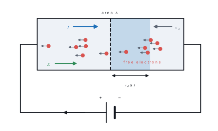
We start from the definition of current as charge per second and reach a formula linking it to the slow drift of the free electrons.
Setting up. A metal wire has cross-sectional area A. It contains n free electrons in every cubic metre, each carrying charge e. Under the applied field they all drift along the wire with the same average speed v_d. Fix your attention on one cross-section of the wire and count the charge that crosses it in a time \Delta t.
Step 1 — find how far an electron travels in the time \Delta t. Distance equals speed times time:
Step 2 — identify which electrons manage to cross the section. Only those starting no further back than l can reach it in time. They are exactly the electrons inside a cylinder of length l and end area A.
Step 3 — find the volume of that cylinder. Volume = area \times length:
Step 4 — find how many electrons are inside it. Number = number per unit volume \times volume:
Step 5 — find the total charge those electrons carry. Charge = number \times charge on each:
Step 6 — use the definition of current, charge per unit time.
Step 7 — cancel \Delta t from top and bottom.
Step 8 — divide both sides by A to get the current density. Current density J is current per unit area:
Result. I = nAv_de, and equivalently J = nev_d.
What it means. The current is large not because the electrons are fast but because n is enormous — about 10^{29} per cubic metre in copper. That is why a drift velocity of a fraction of a millimetre per second still gives amperes of current. Doubling the current in a given wire only doubles v_d.
Conditions used. A steady current; a uniform conductor of constant area A; one kind of charge carrier, all drifting with the same average speed; and n constant along the wire.
- The distance v_d\Delta t and the statement that the electrons which cross are those inside a cylinder of that length.
- Volume = Av_d\Delta t, then number = nAv_d\Delta t.
- Charge \Delta Q = nAv_d\Delta t\,e.
- I = \Delta Q/\Delta t and the cancellation of \Delta t.
Problem. A copper wire of cross-section 1.0\ \text{mm}^{2} carries a current of 5.0\ \text{A}. Copper has n = 8.5\times10^{28} free electrons per cubic metre and e = 1.6\times10^{-19}\ \text{C}. Find the drift velocity, and the time an electron takes to drift 1\ \text{m} along the wire.
Solution. A = 1.0\ \text{mm}^{2} = 1.0\times10^{-6}\ \text{m}^{2}.
The denominator is 8.5\times10^{28}\times10^{-6} = 8.5\times10^{22}, and 8.5\times10^{22}\times1.6\times10^{-19} = 1.36\times10^{4}. Hence
Time for 1\ \text{m}: t = 1/(3.7\times10^{-4}) = 2.7\times10^{3}\ \text{s}, about 45 minutes.
The electrons crawl, but the electric field that sets them moving is established along the whole wire at nearly the speed of light. Electrons everywhere in the circuit — including those already inside the filament — start drifting almost at once. Nothing has to travel from the switch to the bulb.
23.2 Ohm's law, Electrical Resistance, Resistivity, Conductivity
The current flowing through a conductor is directly proportional to the potential difference across its ends, provided its physical conditions (temperature, length, cross-section, nature of material) remain constant: V \propto I, i.e. V = IR.
The constant R is the resistance of the conductor. Its SI unit is the ohm (\Omega): a conductor has a resistance of one ohm if a potential difference of one volt drives a current of one ampere through it.
Experiment shows that for a uniform wire the resistance is proportional to its length l and inversely proportional to its area of cross-section A:
\rho is the resistivity (specific resistance) of the material, with unit \Omega\ \text{m}. Numerically it is the resistance of a piece of the material one metre long and one square metre in cross-section. Its reciprocal is the conductivity
Resistance depends on the material and on the shape and size of the specimen. Resistivity depends only on the material and its temperature. Cutting a wire in half halves its resistance but leaves its resistivity unchanged.
| Material | \rho at 20 °C (Ω m) | Class |
|---|---|---|
| Silver | 1.59\times10^{-8} | conductor |
| Copper | 1.68\times10^{-8} | conductor (house wiring) |
| Aluminium | 2.65\times10^{-8} | conductor (transmission lines) |
| Tungsten | 5.60\times10^{-8} | lamp filament |
| Nichrome | 1.10\times10^{-6} | heating element |
| Germanium | 0.46 | semiconductor |
| Silicon (pure) | \approx 640 | semiconductor |
| Glass | 10^{10} - 10^{14} | insulator |
We start from the drift velocity of the free electrons and reach an explanation of why a metal obeys Ohm's law, together with a formula for its resistivity.
Setting up. A wire of length l and area A carries a current I under a potential difference V. It has n free electrons per unit volume, each of mass m and charge e, and \tau is the average time between two collisions of an electron with the vibrating ions.
Step 1 — write the field inside the wire. The field is uniform along the wire, so from E = V/d with d = l:
Step 2 — write the drift velocity produced by that field. From §23.1, the electron is accelerated for an average time \tau before each collision, giving
Step 3 — start from the current equation of §23.1.
Step 4 — substitute the drift velocity from Step 2.
Step 5 — collect the two factors of e.
Step 6 — substitute the field from Step 1.
Step 7 — divide both sides by I and multiply by the big fraction, so as to make V/I the subject.
Step 8 — recognise V/I as the resistance.
Step 9 — compare this, term by term, with the experimental law R = \rho l/A. The factor multiplying l/A must be the resistivity:
Result. The resistivity of a metal is \rho = m/(ne^{2}\tau), and the resistance is R = \rho l/A.
What it means. Not one of m, n, e or \tau depends on the applied voltage, so at a fixed temperature R is a constant — and V = IR, which is Ohm's law. The formula also explains heating: warmer ions vibrate harder, the electrons collide sooner, \tau falls and \rho rises.
Conditions used. A metal with free electrons as the only carriers; constant temperature (so \tau is fixed); and a uniform wire in a steady state.
For a metal over a moderate range of temperature,
where \alpha is the temperature coefficient of resistance (for copper \alpha \approx 4.0\times10^{-3}\ ^{\circ}\text{C}^{-1}). For semiconductors and electrolytes \alpha is negative: resistance falls as temperature rises, because heating frees many more charge carriers.
Problem. A copper wire is 10\ \text{m} long and 1.0\ \text{mm} in diameter (\rho = 1.68\times10^{-8}\ \Omega\ \text{m}). (a) Find its resistance. (b) The wire is now stretched uniformly to twice its original length. What is its new resistance?
Solution.
(a) A = \pi r^{2} = \pi(0.5\times10^{-3})^{2} = 7.85\times10^{-7}\ \text{m}^{2}.
(b) Stretching does not change the volume, so A'l' = Al. With l' = 2l we get A' = A/2. Hence
In general R \propto l^{2} for a stretched wire of fixed volume.
23.3 Current-voltage relations: Ohmic and Non-Ohmic resistance
A conductor that obeys Ohm's law is ohmic: its I–V graph is a straight line through the origin, and R = V/I is the same at every point. A conductor whose I–V graph is not a straight line through the origin is non-ohmic.
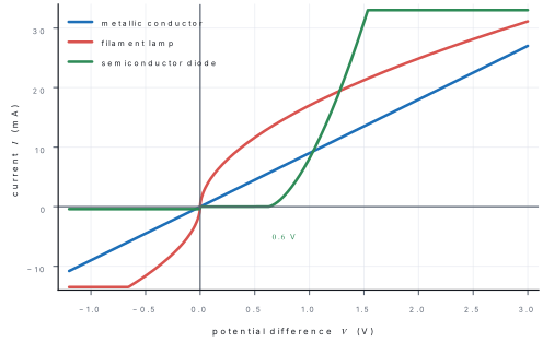
| Ohmic | Non-ohmic |
|---|---|
| I–V graph is a straight line through origin | graph is curved, or does not pass through origin |
| R = V/I constant | R = V/I changes with V |
| Same behaviour for either polarity | may depend on the direction of current |
| Metals at constant temperature, nichrome, carbon resistors | filament lamp, diode, thermistor, electrolyte, gas discharge tube, transistor |
A filament lamp is non-ohmic only because the current heats the tungsten: as V rises the filament goes from about 300 K to about 2500 K, its resistance rises several times, and the graph bends towards the V-axis. A junction diode conducts almost nothing until the forward voltage reaches about 0.6\ \text{V} (silicon), and blocks current completely in reverse.
For a non-ohmic device, the resistance at a point is V/I (the slope of the chord from the origin), not dV/dI (the slope of the tangent, which is the dynamic resistance). For an ohmic conductor the two happen to be equal — which is why students confuse them.
23.4 Resistances in series and parallel
Any combination of resistors between two terminals can be replaced by one equivalent resistance R_{eq} that would draw the same current from the same supply.
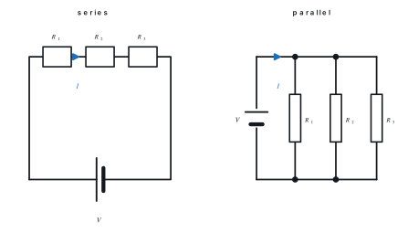
We start from the two facts that define a series connection and reach the rule for the single resistor that could replace the three.
Setting up. Three resistors R_1, R_2, R_3 are joined end to end across a supply of p.d. V. The p.d. across them are V_1, V_2, V_3.
Step 1 — state why the current is the same in all three. There is only one path, and charge does not pile up anywhere, so whatever flows into R_1 must flow out of R_3:
Step 2 — state why the voltages add. Moving from one end of the chain to the other, the total fall in potential is the sum of the separate falls:
Step 3 — write each p.d. from Ohm's law, V = IR.
Step 4 — substitute these into Step 2.
Step 5 — write the same total p.d. for the single equivalent resistor. By definition R_{eq} carries the same current I at the same total p.d. V:
Step 6 — set the two expressions for V equal.
Step 7 — divide every term by I, which is the same throughout by Step 1:
Result. In series the resistances simply add.
What it means. Each extra resistor adds more length of "difficult path", so the total is always larger than the largest single resistor.
Conditions used. One single path with nothing joined at the junctions, and each resistor obeying Ohm's law at the temperature it reaches.
We start from the two facts that define a parallel connection and reach the rule for the single replacement resistor.
Setting up. Three resistors R_1, R_2, R_3 are connected between the same two points, across a p.d. V. They carry currents I_1, I_2, I_3.
Step 1 — state why the p.d. is the same across all three. Every resistor has its two ends joined to the same two points, so each feels the same potential difference:
Step 2 — state why the currents add. At the junction the incoming current splits into the three branches, and by Kirchhoff's first law nothing is lost:
Step 3 — write each branch current from Ohm's law, I = V/R.
Step 4 — substitute these into Step 2.
Step 5 — write the same total current for the single equivalent resistor.
Step 6 — set the two expressions for I equal.
Step 7 — divide every term by V, which is the same for all of them by Step 1:
Step 8 — write the special case of just two resistors. Add the two fractions over a common denominator and turn the result upside down:
Result. In parallel the reciprocals add; for two resistors this is "product over sum".
What it means. Each new branch gives the current another road to travel, so the combination is always smaller than the smallest resistor in it. This is why adding appliances in a house circuit lowers the total resistance and raises the total current drawn.
Conditions used. All the resistors share the same two nodes, the connecting wires have negligible resistance, and each resistor is ohmic.
In a parallel pair the current divides in the inverse ratio of the resistances:
Problem. A battery of emf 12\ \text{V} and negligible internal resistance is connected to a 2\ \Omega resistor in series with a parallel combination of 3\ \Omega and 6\ \Omega. Find (a) the equivalent resistance, (b) the current drawn from the battery, and (c) the current in each parallel branch.
Solution.
(a) Parallel part: R_p = \dfrac{3\times6}{3+6} = \dfrac{18}{9} = 2\ \Omega. Total: R_{eq} = 2 + 2 = 4\ \Omega.
(b) I = \dfrac{V}{R_{eq}} = \dfrac{12}{4} = 3\ \text{A}.
(c) Voltage across the parallel section: V_p = IR_p = 3\times2 = 6\ \text{V}. So I_{3} = 6/3 = 2\ \text{A} and I_{6} = 6/6 = 1\ \text{A}.
Check: 2 + 1 = 3\ \text{A}, as required.
Kirchhoff's laws
Many networks — a bridge, or two cells feeding one resistor — cannot be reduced by series and parallel rules at all. Kirchhoff's two laws solve every such network.
First law (junction law). The algebraic sum of the currents meeting at any junction is zero: \sum I = 0. Currents entering the junction are taken positive and those leaving negative. This is conservation of charge — charge does not pile up at a junction.
Second law (loop law). In any closed loop, the algebraic sum of the emfs equals the algebraic sum of the IR products: \sum E = \sum IR. This is conservation of energy — a unit charge taken once round a loop returns to the same potential.
- Choose a direction for each unknown current and mark it. A negative answer simply means the real current is the other way.
- Go round the loop in one fixed sense (say clockwise).
- A resistance traversed along the assumed current gives +IR; against it, -IR.
- A cell traversed from - to + inside it gives +E; from + to - gives -E.
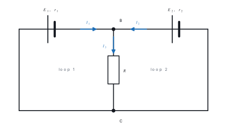
Problem. In the network of the figure, E_1 = 8\ \text{V} with r_1 = 1\ \Omega (left branch), E_2 = 10\ \text{V} with r_2 = 4\ \Omega (right branch), and the middle branch BC is a R = 2\ \Omega resistor. Find the current in each branch.
Solution. Let I_1 and I_2 flow towards B in the left and right branches. By the junction law at B the middle branch carries I_3 = I_1 + I_2 downwards.
Loop 1 (left cell and R):
Loop 2 (right cell and R):
From the first, I_2 = (8-3I_1)/2. Substituting in the second:
Then I_2 = (8-6)/2 = 1\ \text{A} and I_3 = 3\ \text{A}.
Check with energy: the cells supply 8(2) + 10(1) = 26\ \text{W}; the resistors dissipate 2^{2}(1) + 1^{2}(4) + 3^{2}(2) = 4 + 4 + 18 = 26\ \text{W}.
The Wheatstone bridge
The Wheatstone bridge is the standard way of measuring an unknown resistance accurately, because at balance the answer depends only on a ratio — no ammeter or voltmeter reading is needed.
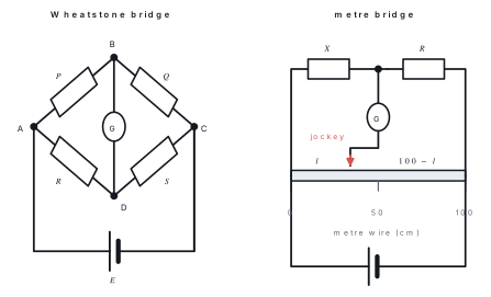
We start from the fact that the galvanometer reads zero and reach a simple relation between the four arm resistances.
Setting up. Four resistances P, Q, R, S form the arms AB, BC, AD and DC of a diamond. A galvanometer joins B to D, and a cell is connected across A and C. The bridge is called balanced when the galvanometer shows no deflection.
Step 1 — say what "no deflection" means for the potentials. No current flows through the galvanometer only if there is no potential difference driving it, so B and D must be at the same potential:
Step 2 — follow the currents. Since nothing leaks away at B into the galvanometer, the current I_1 that enters through P carries straight on through Q. In the same way the current I_2 through R carries on through S.
Step 3 — write the p.d. across the two upper arms. Ohm's law gives
Step 4 — these two are equal, because V_B = V_D from Step 1.
Step 5 — write the p.d. across the two lower arms.
Step 6 — these two are also equal, for the same reason.
Step 7 — divide equation (1) by equation (2). Both sides are non-zero, so the division is allowed:
Step 8 — cancel I_1 on the left and I_2 on the right.
Step 9 — rearrange to find the unknown arm. If P, Q and R are known and S is the unknown, cross-multiply and divide:
Result. The bridge is balanced when P/Q = R/S, and the unknown resistance is then S = QR/P.
What it means. The currents I_1 and I_2 cancelled, so the answer does not depend on the emf of the cell, on its internal resistance, or on the resistance of the galvanometer and the leads. Only a ratio of resistances is measured, which is why the method is so accurate.
Conditions used. The galvanometer must read exactly zero (true balance), all four arms must be ohmic, and the resistances must not drift as they warm up.
- A labelled diagram of the diamond with P, Q, R, S, the galvanometer between B and D, and the cell across A and C.
- The statement V_B = V_D at balance, with the reason.
- The two current paths I_1 through P and Q, I_2 through R and S.
- The two equations I_1P = I_2R and I_1Q = I_2S.
- Dividing one by the other and cancelling the currents to get P/Q = R/S.
At balance the galvanometer carries no current, so its resistance, the resistance of the connecting wires and the emf and internal resistance of the cell do not enter the answer at all. Only a ratio of resistances does. That is why bridge and potentiometer methods are called null methods and are far more accurate than an ammeter–voltmeter measurement.
The metre bridge
The metre bridge is the Wheatstone bridge built around a uniform resistance wire exactly one metre long. The unknown X is put in the left gap and a resistance box R in the right gap; the two parts of the wire on either side of the jockey replace the other two arms. Because the wire is uniform, its resistance is proportional to its length, so if the balance point is at l cm from the left end,
Problem. In a metre bridge the unknown resistance X is in the left gap and a 5\ \Omega resistance box in the right gap. The balance point is found at 60\ \text{cm} from the left end. (a) Find X. (b) X is a wire of length 1.0\ \text{m} and diameter 0.40\ \text{mm}; find its resistivity.
Solution.
(a)
(b) A = \pi r^{2} = \pi(0.20\times10^{-3})^{2} = 1.26\times10^{-7}\ \text{m}^{2}.
Take readings with l between about 40 and 60\ \text{cm} by choosing a suitable R. Near the ends, a small error in l produces a large percentage error in X, and the unaccounted resistance of the end connections (end error) matters most there.
Converting a galvanometer into an ammeter and a voltmeter
A galvanometer is a sensitive current detector with resistance G that gives full-scale deflection for a very small current I_g. Series and parallel combinations turn it into a practical meter.
Ammeter. Connect a small resistance S (a shunt) in parallel, so that most of the current bypasses the coil. If the meter is to read up to I, then the shunt carries I - I_g and, since both have the same potential difference,
Voltmeter. Connect a large resistance R (a multiplier) in series, so that only I_g flows when the full voltage V is applied:
| Ammeter | Voltmeter | |
|---|---|---|
| Made by | low shunt in parallel | high multiplier in series |
| Connected | in series with the element | in parallel with the element |
| Ideal resistance | zero | infinite |
| Effect of a real meter | slightly reduces the current | slightly reduces the pd |
Problem. A galvanometer of resistance 100\ \Omega gives full-scale deflection for 1.0\ \text{mA}. Convert it into (a) an ammeter reading 0-1.0\ \text{A} and (b) a voltmeter reading 0-10\ \text{V}.
Solution.
(a)
so a shunt of about 0.1\ \Omega is connected in parallel.
(b)
so a 9900\ \Omega multiplier is connected in series.
23.5 Potential divider
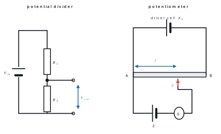
Two resistors in series across a supply form a potential divider (voltage divider). The supply voltage divides between them in the ratio of their resistances, so the output taken across R_2 is
If the two resistors are the two parts of a single uniform wire or a track with a sliding contact, V_{out} can be varied continuously from 0 to V_{in} — this is how a volume control works. A rheostat (two terminals) can only reduce the voltage down to a limit set by the load; a potential divider (three terminals) can take the output all the way down to zero, which is why it is preferred.
The potentiometer
A potentiometer is a potential divider made from a long uniform resistance wire AB (usually 4 m or 10 m of manganin, arranged in 1 m lengths) carrying a steady current from a driver cell of emf E_0. Because the wire is uniform, the potential falls uniformly along it. The potential gradient is
and the pd across the first l metres is V = kl.
The cell being tested is connected with its positive terminal to A, through a galvanometer to the jockey. The jockey is slid until the galvanometer reads zero. At that balance point the cell drives no current, so the pd it would supply is exactly balanced by the pd kl across the wire, and the reading is the cell's emf, not its terminal pd:
Comparison of two emfs. Balancing the two cells separately at lengths l_1 and l_2 gives E_1 = kl_1 and E_2 = kl_2, hence
Internal resistance of a cell. First balance the cell on open circuit at length l_1, so E = kl_1. Then close a known resistance R across the cell and re-balance at l_2, so the terminal pd is V = kl_2. Since E = I(R+r) and V = IR,
Problem. A potentiometer wire AB is 10.0\ \text{m} long and the whole 2.0\ \text{V} of the driver cell falls across it. A cell connected in the secondary circuit balances at 7.50\ \text{m} from A. When a 4.0\ \Omega resistor is connected across this cell, the balance length becomes 6.00\ \text{m}. Find (a) the potential gradient, (b) the emf of the cell and (c) its internal resistance.
Solution.
(a) k = \dfrac{2.0}{10.0} = 0.20\ \text{V m}^{-1}.
(b) E = kl_1 = 0.20\times7.50 = 1.50\ \text{V}.
(c) Terminal pd V = kl_2 = 0.20\times6.00 = 1.20\ \text{V}, so
...the positive terminals of the driver cell and the test cell are not both connected to the same end A, or if the emf of the test cell is greater than the pd across the whole wire. In both cases the galvanometer deflects the same way at every point of the wire — that is the symptom to recognise in the lab.
23.6 Electromotive force of a source, internal resistance
The electromotive force E of a source is the energy given to each coulomb of charge driven round the complete circuit; it equals the pd across the terminals of the source on open circuit. The terminal potential difference V is the pd across the terminals when the source is actually delivering current. Both are measured in volts; emf is not a force.
Every real cell has some resistance of its own — the resistance of its electrolyte and electrodes — called the internal resistance r. When the cell drives a current, part of the emf is used up inside the cell itself.
We start from the energy given to each coulomb by the cell and reach a formula for the voltage you would actually measure across its terminals.
Setting up. A cell of emf E and internal resistance r drives a steady current I through an external resistance R. The emf is the energy the cell gives to each coulomb; that energy has to be shared between the two resistances the charge meets.
Step 1 — apply conservation of energy per coulomb around the loop. The energy supplied to each coulomb equals the energy it gives up in the outside circuit plus the energy it gives up inside the cell:
Step 2 — write each p.d. from Ohm's law. The same current I passes through both, since the cell and R are in one single loop:
Step 3 — take I out as a common factor and solve for the current.
Step 4 — say what the voltmeter across the terminals actually reads. The terminals are the two ends of R, so the terminal p.d. is
Step 5 — go back to Step 2 and make IR the subject. Subtract Ir from both sides:
Step 6 — replace IR by V, using Step 4.
Result. The terminal potential difference is V = E - Ir, and the current in the circuit is I = E/(R+r).
What it means. The term Ir is the "lost volts" — the part of the emf spent pushing the current through the cell's own resistance. It also gives a way to measure E and r: a graph of V against I is a straight line whose intercept is E and whose slope is -r.
Conditions used. A steady current in a single loop; E and r treated as constant (in a real cell r grows as the cell ages); and the cell is discharging. If the cell is being charged, the current is reversed and V = E + Ir instead.
So the terminal pd is always less than the emf while the cell is discharging, and the graph of V against I is a straight line of intercept E and slope -r. If the terminals are short-circuited (R = 0), the current is limited only by r: I_{max} = E/r. This is why a "dead" torch cell, whose r has grown large, still shows nearly 1.5\ \text{V} on a voltmeter but cannot light a bulb.
| Connection | Equivalent emf | Equivalent internal resistance | Use when |
|---|---|---|---|
| n identical cells in series | nE | nr | R is much larger than r |
| n identical cells in parallel | E | r/n | R is much smaller than r |
Problem. A cell gives a terminal pd of 1.40\ \text{V} when it supplies 0.40\ \text{A}, and 1.20\ \text{V} when it supplies 0.80\ \text{A}. Find the emf and internal resistance of the cell, and the current if its terminals were short-circuited.
Solution. Using V = E - Ir twice:
Subtracting the second from the first: 0.20 = 0.40r, so r = 0.50\ \Omega. Then E = 1.40 + 0.40(0.50) = 1.60\ \text{V}.
Short-circuit current: I = E/r = 1.60/0.50 = 3.2\ \text{A}.
23.7 Work and power in electrical circuits
We start from the definition of potential difference and reach the three forms of the power formula.
Setting up. A steady current I flows for a time t through a resistor R across which the potential difference is V.
Step 1 — use the definition of potential difference. Potential difference is work done per unit charge, so the work done on a charge Q falling through V is
Step 2 — express the charge in terms of the current. Current is charge per second, so in a time t a steady current I carries
Step 3 — substitute this into Step 1.
Step 4 — divide by the time to get the power. Power is work done per second:
Step 5 — cancel t.
Step 6 — get the second form. For an ohmic resistor, Ohm's law gives V = IR; put that in place of V:
Step 7 — multiply out.
Step 8 — get the third form. Start again from P = VI and this time replace I by V/R:
Step 9 — multiply out.
Result.
and the heat produced in a time t is H = I^{2}Rt.
What it means. All three expressions give the same number for the same resistor — choose whichever uses the two quantities you already know. In a series circuit the current is common, so P = I^{2}R is the quick one; in a parallel circuit the voltage is common, so P = V^{2}/R is.
Conditions used. Steady current and steady p.d.; and Steps 6 to 9 need the element to be ohmic, so that V = IR holds. The general form P = VI works for any device, ohmic or not.
For a source of emf E delivering current I, the total power generated is P = EI; of this, I^{2}r is wasted inside the source and VI = I^2R reaches the external circuit.
In a pure resistance all the electrical work appears as heat:
The heat produced is proportional to (i) the square of the current, (ii) the resistance, and (iii) the time. In calories, H = I^{2}Rt/4.2.
Use P = I^{2}R when the elements are in series (same I): the largest resistance dissipates most power. Use P = V^{2}/R when they are in parallel (same V): the smallest resistance dissipates most power. Choosing the right form makes "which bulb is brighter?" questions immediate.
Two bulbs rated 100\ \text{W} and 60\ \text{W} at 220\ \text{V} have resistances 484\ \Omega and 807\ \Omega. Joined in series, the same current flows, so P = I^2R makes the 60\ \text{W} bulb glow brighter. Power ratings only hold at the rated voltage.
Electrical energy is sold in kilowatt-hours: 1\ \text{kWh} = 1000\ \text{W} \times 3600\ \text{s} = 3.6\times10^{6}\ \text{J}. This is the "unit" on a NEA bill.
Problem. An electric heater is marked 1500\ \text{W}, 220\ \text{V}. (a) Find its resistance and the current it draws. (b) How long does it take to heat 2.0\ \text{kg} of water from 20\ ^{\circ}\text{C} to 100\ ^{\circ}\text{C}, assuming no heat is lost? Take c = 4200\ \text{J kg}^{-1}\ ^{\circ}\text{C}^{-1}. (c) If it runs 2 hours a day for 30 days, what does it cost at Rs 10 per unit?
Solution.
(a) R = \dfrac{V^{2}}{P} = \dfrac{220^{2}}{1500} = \dfrac{48400}{1500} = 32.3\ \Omega; I = \dfrac{P}{V} = \dfrac{1500}{220} = 6.8\ \text{A}.
(b) Heat needed: Q = mc\Delta\theta = 2.0\times4200\times80 = 6.72\times10^{5}\ \text{J}.
(c) Energy = 1.5\ \text{kW}\times2\ \text{h}\times30 = 90\ \text{kWh}, so the cost is 90\times10 = Rs 900.
Chapter summary
- Current is I = dQ/dt; in a metal I = nAv_de and J = I/A = nev_d, with a drift velocity of order 10^{-4}\ \text{m s}^{-1}.
- Ohm's law: V = IR at constant temperature. R = \rho l/A, \sigma = 1/\rho, and microscopically \rho = m/(ne^{2}\tau).
- Ohmic conductors give a straight I–V line through the origin; lamps, diodes and thermistors are non-ohmic.
- Series: R_{eq} = R_1+R_2+R_3. Parallel: 1/R_{eq} = 1/R_1+1/R_2+1/R_3.
- Kirchhoff: \sum I = 0 at a junction (charge conservation); \sum E = \sum IR round a loop (energy conservation).
- Wheatstone bridge balances when P/Q = R/S; the metre bridge form is X = Rl/(100-l).
- Galvanometer to ammeter: shunt S = I_gG/(I-I_g) in parallel. To voltmeter: multiplier R = V/I_g - G in series.
- Potential divider: V_{out} = V_{in}R_2/(R_1+R_2). Potentiometer: E = kl, E_1/E_2 = l_1/l_2, and r = R(l_1-l_2)/l_2.
- For a source, I = E/(R+r) and V = E - Ir; power P = VI = I^{2}R = V^{2}/R and heat H = I^{2}Rt.
Practice questions
Group A — Multiple choice (1 mark each)
- The drift velocity of free electrons in a copper wire carrying a normal current is of the order of [1]a10^{8}\ \text{m s}^{-1}b10^{5}\ \text{m s}^{-1}c10^{-4}\ \text{m s}^{-1}d10^{-10}\ \text{m s}^{-1}
- A wire of resistance R is stretched uniformly until its length is doubled. Its new resistance is [1]aR/2b2Rc4RdR/4
- Three resistors of 6\ \Omega each are connected in parallel. The equivalent resistance is [1]a18\ \Omegab6\ \Omegac3\ \Omegad2\ \Omega
- Kirchhoff's junction law is a statement of the conservation of [1]aenergybchargecmomentumdmass
- A galvanometer is converted into an ammeter by connecting [1]aa high resistance in seriesba low resistance in seriesca high resistance in parallelda low resistance in parallel
- A 100\ \text{W} and a 60\ \text{W} bulb, both rated 220\ \text{V}, are joined in series across 220\ \text{V}. Then [1]athe 100\ \text{W} bulb is brighterbthe 60\ \text{W} bulb is brightercboth are equally brightdneither glows
Answers to Group A
1. (c) — from v_d = I/nAe, a few tenths of a millimetre per second.
2. (c) — volume is constant, so A halves and R \propto l^{2} gives 4R.
3. (d) — 1/R_{eq} = 3/6, so R_{eq} = 2\ \Omega.
4. (b) — charge cannot accumulate at a junction.
5. (d) — a low shunt in parallel carries the excess current.
6. (b) — same current in series, and P = I^{2}R with R_{60} > R_{100}.
Group B — Short answer (5 marks each)
- Define drift velocity and derive the relation I = nAv_de for a metallic conductor. [5]
- Distinguish between ohmic and non-ohmic conductors with one I–V graph and two examples of each. [5]
- Derive expressions for the equivalent resistance of three resistors connected(a) in series and(b) in parallel. [5]
- A battery of emf 10\ \text{V} and negligible internal resistance is connected to a 2\ \Omega resistor in series with a parallel combination of 4\ \Omega and 12\ \Omega. Find the equivalent resistance, the current drawn, and the current in each parallel branch. [5]
- A cell of emf 2.0\ \text{V} and internal resistance 0.5\ \Omega is connected across a 4.5\ \Omega resistor. Find the current, the terminal potential difference, and the power dissipated in the external resistor. [5]
- In a metre bridge experiment the unknown resistance X is in the left gap and a 6\ \Omega resistance box in the right gap. The balance point is at 40\ \text{cm} from the left end. Find X, and state where the balance point would be if the two were interchanged. [5]
Answers to Group B
4. Parallel part: 4\times12/16 = 3\ \Omega; total = 2+3 = 5\ \Omega. Current drawn I = 10/5 = 2\ \text{A}. Pd across the parallel part = 2\times3 = 6\ \text{V}, so I_4 = 6/4 = 1.5\ \text{A} and I_{12} = 6/12 = 0.5\ \text{A} (sum = 2\ \text{A}, as it must be).
5. I = E/(R+r) = 2.0/5.0 = 0.40\ \text{A}; V = IR = 0.40\times4.5 = 1.8\ \text{V} (or E - Ir = 2.0-0.2); P = I^{2}R = 0.16\times4.5 = 0.72\ \text{W}.
6. X = R\,l/(100-l) = 6\times40/60 = 4\ \Omega. On interchanging, the balance length measured from the left end becomes 100-40 = 60\ \text{cm}, since now R/X = l'/(100-l') gives 6/4 = 60/40.
1., 2., 3. are bookwork: see §23.1, §23.3 and §23.4 respectively. Marks are awarded for the labelled diagram, the statement of the principle, and each algebraic step.
Group C — Long answer (8 marks each)
- (a) State Kirchhoff's laws of electrical networks and name the conservation principle behind each. [2](b) Draw a Wheatstone bridge and derive its balance condition. [3](c) In a metre bridge, an unknown resistance in the left gap balances against 3\ \Omega in the right gap at 75\ \text{cm} from the left end. Find the unknown resistance. [3]
- (a) Define emf and terminal potential difference and derive V = E - Ir. [3](b) Describe how a potentiometer is used to measure the internal resistance of a cell, deriving the formula used. [3](c) A cell balances at 250\ \text{cm} of a potentiometer wire; with a 5\ \Omega resistor across it the balance length falls to 200\ \text{cm}. Find its internal resistance. [2]
- (a) Derive P = I^{2}R from the definition of potential difference, and state Joule's law of heating. [3](b) A battery of emf 12\ \text{V} and internal resistance 1\ \Omega is connected to a 3\ \Omega resistor in series with a parallel combination of 6\ \Omega and 12\ \Omega. Find the current drawn, the terminal potential difference, and the power dissipated in the 6\ \Omega resistor. [5]
Answers to Group C
1.(c) X = R\,l/(100-l) = 3\times75/25 = 9\ \Omega.
2.(c) r = R(l_1-l_2)/l_2 = 5\times(250-200)/200 = 5\times0.25 = 1.25\ \Omega.
3.(b) Parallel part = 6\times12/18 = 4\ \Omega; total = 3+4+1 = 8\ \Omega. Current I = 12/8 = 1.5\ \text{A}. Terminal pd V = E - Ir = 12 - 1.5 = 10.5\ \text{V}. Pd across the parallel part = 1.5\times4 = 6\ \text{V}, so the 6\ \Omega resistor carries 1.0\ \text{A} and dissipates P = I^{2}R = 1.0^{2}\times6 = 6\ \text{W}.
1.(a), 1.(b), 2.(a), 2.(b), 3.(a) are bookwork: see the boxed statements in §23.4, the Wheatstone derivation, §23.6 and §23.7.
Practise more: Physics question bank